Multiple resonance tube thermo-acoustic engine

A thermoacoustic engine, multi-resonance technology, applied to machines/engines, mechanisms that generate mechanical power, compressors, etc., can solve problems such as engine operating frequency jumps, restricting the process of practicality, and the inability of resonant tubes to play a role, reducing Viscous flow loss, improving heat-to-power conversion efficiency, and suppressing nonlinear effects

Inactive Publication Date: 2007-10-17
ZHEJIANG UNIV
View PDF0 Cites 11 Cited by
  • Summary
  • Abstract
  • Description
  • Claims
  • Application Information

AI Technical Summary

Problems solved by technology

At present, the common means to adjust the operating frequency of the thermoacoustic engine are to change the type of working fluid, change the length and diameter of the resonant tube, etc., but these means are restricted to varying degrees in practice
In addition, some studies have shown that if the engine frequency is reduced blindly by extending the resonance tube, it will cause a jump in the operating frequency of the engine, making its frequency higher and unstable
[0008] In summary, the resonant tube plays a vital role in the thermoacoustic engine, but the optimal design of the resonant tube is limited by many aspects
First of all, there is only one optimal structural size of the resonant tube under a certain working condition. When the working state of the engine changes, the resonant tube cannot play its due role; It restricts its practical process, and the main part of the thermoacoustic engine is the resonant tube; again, based on the current understanding of the transmission characteristics of the sound wave, the linear thermoacoustic theory is the only effective design tool, and the nonlinear thermoacoustic theory has just started. The resonant tube has a strong nonlinear effect, so it is not possible to optimize the design of the resonant tube simply based on existing theories

Method used


Image

  • Multiple resonance tube thermo-acoustic engine
  • Multiple resonance tube thermo-acoustic engine
  • Multiple resonance tube thermo-acoustic engine

Examples


Embodiment Construction

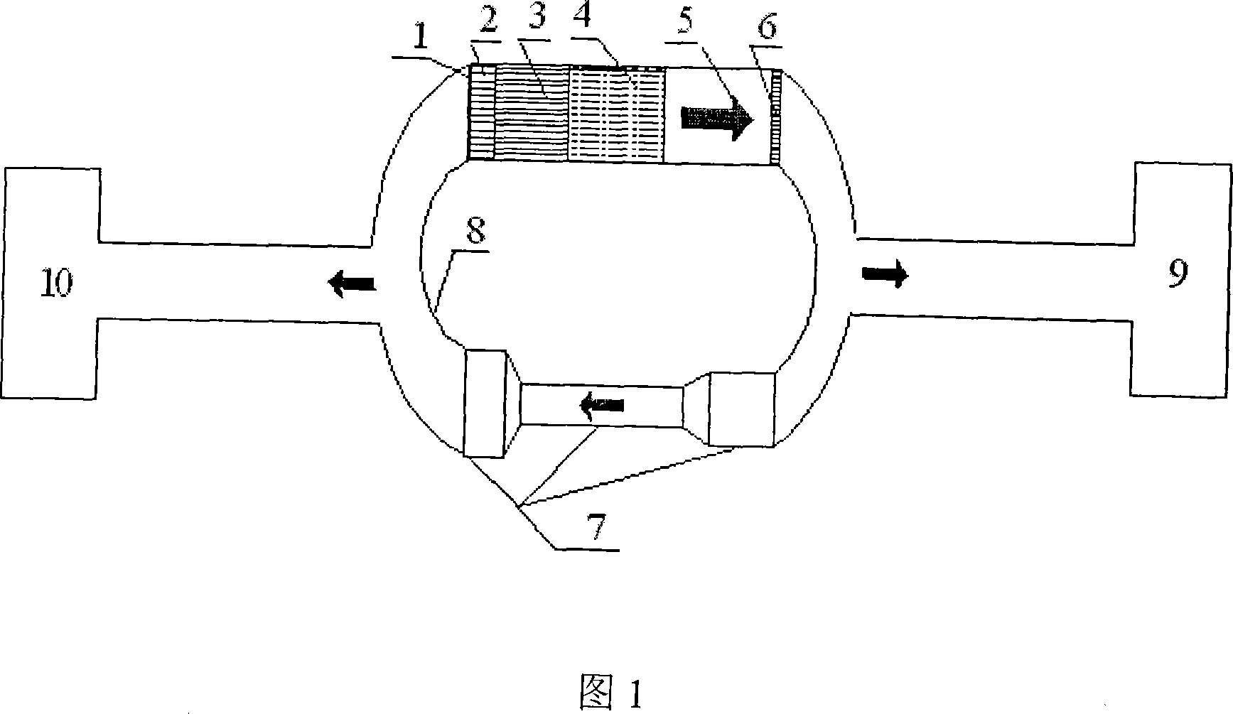
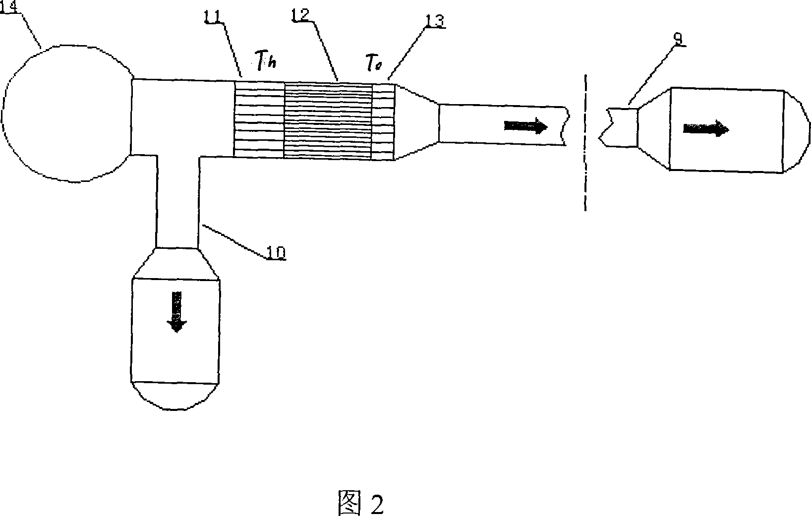
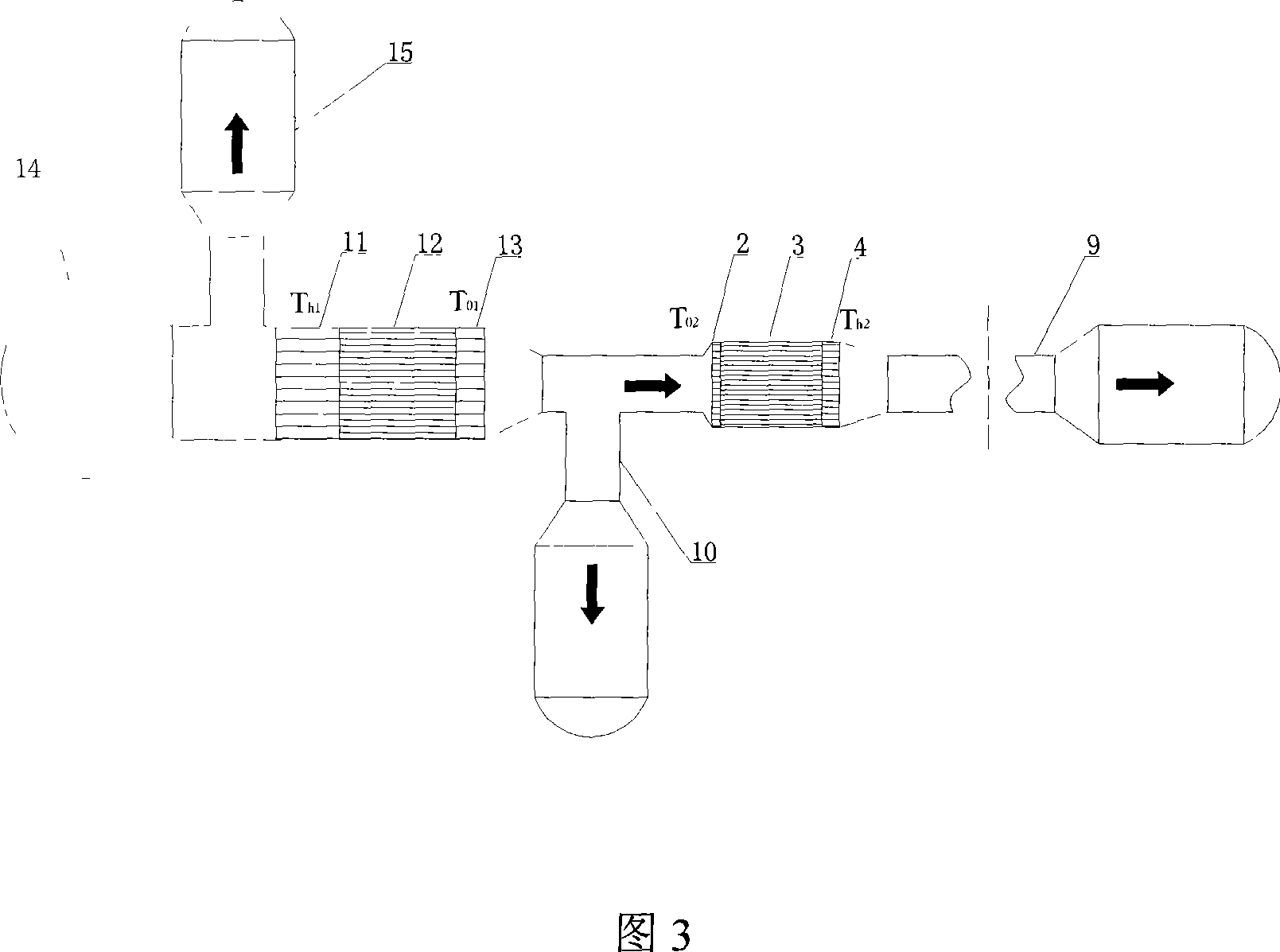
[0020] The resonant tube of a thermoacoustic engine is usually a straight tube with a specific inner diameter. In order to realize the 1 / 4 wavelength sound field condition, an air reservoir is often set at the end of the straight tube. The single resonant tube traveling wave thermoacoustic engine has a traveling wave loop and a straight resonant path, and an air reservoir is arranged at the end of the resonant tube. The engine has a main cooler, a regenerator, a heater, a heat buffer pipe, a feedback loop, a sound capacity, and a DC suppression component connected in sequence, and the resonance pipe is drawn out from the tee. The single resonant tube standing wave thermoacoustic engine has a high-temperature cavity, a hot-end heat exchanger, a thermoacoustic plate stack, and a cold-end heat exchanger connected in sequence. The resonant tube is connected to the cold-end heat exchanger through a pipe diameter transition tube. An air reservoir is also arranged at the end, and par...


PUM


Abstract

The present invention discloses a multiple resonance tube thermo acoustic engine which disposes two or more resonance tubes on a thermo acoustic engine. The thermo acoustic engine is a travelling wave thermo acoustic engine, a standing wave thermo acoustic engine or a travelling wave and standing wave mixing type thermo acoustic engine. The resonance tube is an equal diameter tube, a variable diameter tube or the combination to them. The present invention optimizes the sound field distribution of a thermo acoustic engine, reduces the glutinosity flow lost for a thermo acoustic heat regenerator, restrains the nonlinear effect in the tube, improves the adaptive ability for the engine, and achieves the object of improving heat conversion efficiency. In addition, the present invention can conveniently adjust the work frequency of the thermo acoustic engine and optimize the frequency matching between the thermo acoustic engine and other driven load such as pulse tube refrigerator by coupling different resonance tube structures.

Description

technical field [0001] The invention relates to an engine, in particular to a multi-resonance tube thermoacoustic engine. Background technique [0002] Modern industrial production, space technology and military engineering have put forward higher and higher requirements for the reliability and life of cryogenic refrigerators. The split Stirling refrigerators and G-M refrigerators that have been widely used cannot fully meet these requirements. The key reason is that there are at least two moving parts in these mechanical refrigerators: the compressor and the ejector, which become the long-term influence of the refrigerator. Major obstacle to reliable operation. The pulse tube refrigerators that appeared in the 1960s and 1970s have improved reliability and lifespan because there are no mechanical moving parts at the low temperature end. After more than ten years of theoretical and experimental research, pulse tube refrigerators have gradually entered the practical stage. ...

Claims


Application Information

Patent Timeline
Patent Type & Authority Applications(China)
IPC IPC(8): F03G7/00
CPCF25B2309/1403F25B2309/1413F25B9/145F25B2309/1405
Inventor 孙大明邱利民肖勇王波
Owner ZHEJIANG UNIV
Why Eureka
Try Eureka