Ground heater device

A floor heating and heating layer technology, which is applied in hot water central heating systems, household heating, lighting and heating equipment, etc., can solve the problems of inapplicability of tile floors, achieve low cost, not easy to crack or distort, and balance the ground temperature Effect

Inactive Publication Date: 2007-10-17
李书新
View PDF1 Cites 4 Cited by
  • Summary
  • Abstract
  • Description
  • Claims
  • Application Information

AI Technical Summary

Problems solved by technology

This utility model is only for wooden floors, and tile floors are not applicable

Method used


Image

  • Ground heater device
  • Ground heater device

Examples


Embodiment Construction

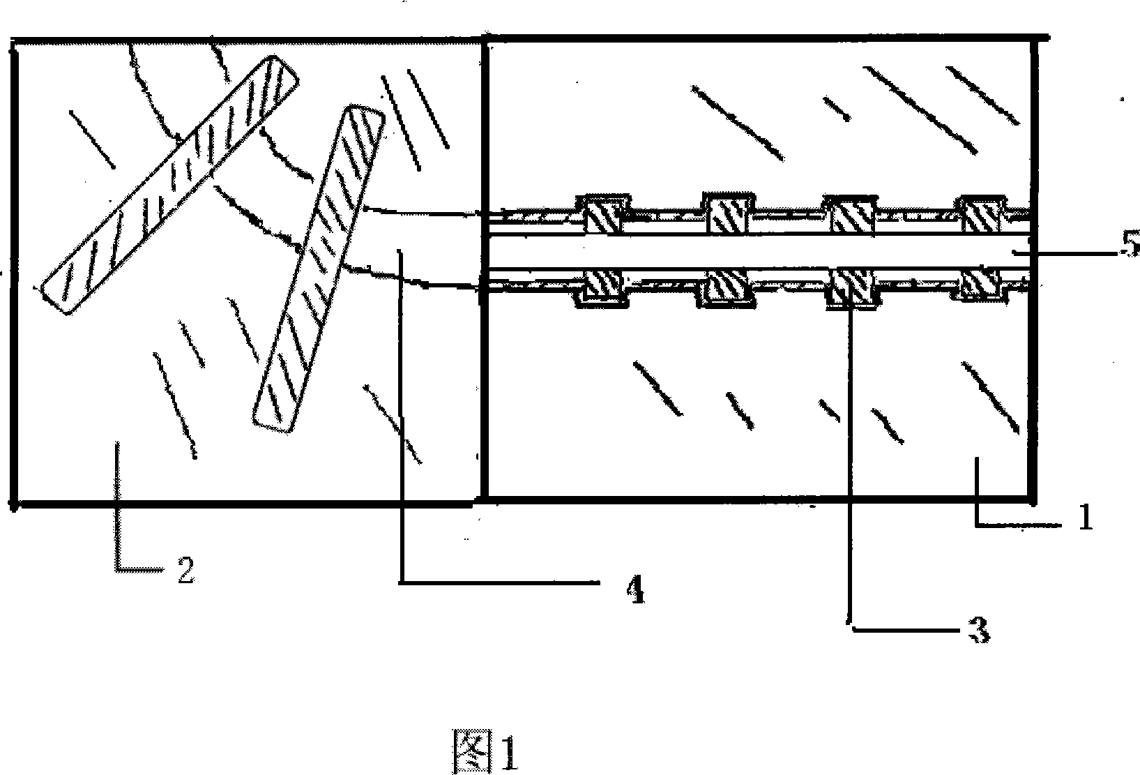
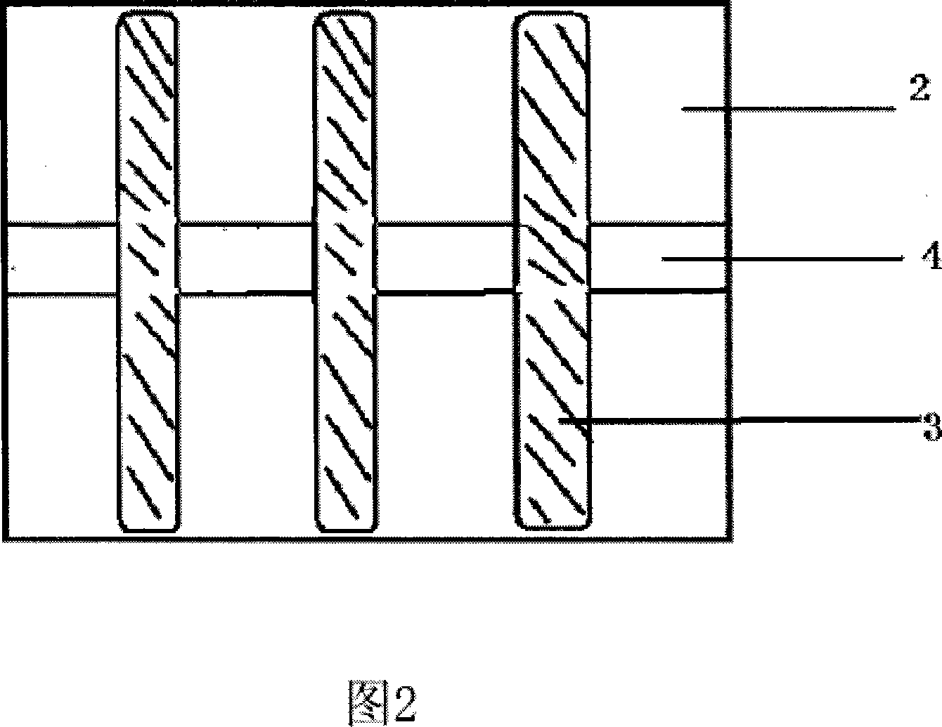
[0012] 1. A floor heating device, consisting of an upper heating layer 1, a lower heating layer 2, a heating tank 4, a heat conducting rod 3 and a heat conducting pipe 5. The upper 1 of the heating layer and the lower 2 of the heating layer can be divided, and the heating grooves 4 of the upper and lower heating layers correspond to each other. According to the surface area, lay the heating layer lower layer 2 on the ground, spread the heat conduction pipe 5 in the heating tank 4 of the heating layer lower layer 2, the heat conduction rod 3 is squeezed below by the heating pipe 5, and then add the heating layer 1 layer, corresponding to the teeth of the upper and lower heating grooves 4. The heat pipe 5 is a hot water circulation system, and the two ends of the heat pipe 5 are connected with the water supply valve.

[0013] 2. A floor heating device, consisting of an upper heating layer 1, a lower heating layer 2, a heating tank 4, a heat conducting rod 3 and a heat conductin...


PUM


Abstract

The invention relates to a geothermal equipment which comprises upper heating layer, lower heating layer, heating groove, heat conductive rod and heat conductive pipe. The heat conductive pipe is tiled in the heating groove of the heating layer, and the heat conductive rod is extruded by the heating pipe and under the same and is disposed between two heating layers. Woodiness floor or ceramic tile floor are paved on the upper heating layer as the equipment is used. The invention has simple structure, and can heat floor uniformly thereby increasing thermal efficient and saving energy.

Description

technical field [0001] The invention relates to an indoor heating device, in particular to a geothermal heating device. Background technique [0002] In northern my country, traditional heating devices use radiators and heating pipes for heating and heating, but the heating is slow, the heating is uneven and insufficient, and the surface temperature is relatively low. When the heat is dissipated, the indoor temperature also drops sharply, and such a radiator group also takes up a lot of space. These cannot meet the living needs of the people. [0003] In recent years, a geothermal heating method has emerged. This heating method is to make an insulation layer on the concrete, lay pipes on the insulation layer, and fill the pipes with concrete to lay the floor surface together. In this way, the load of the building is large. The cost is also relatively high. For example, the utility model patent (notification number CN2474965Y, date of announcement: January 30, 2002) is an ...

Claims


Application Information

Patent Timeline
Patent Type & Authority Applications(China)
IPC IPC(8): F24D3/14
Inventor 李书新
Owner 李书新
Why Eureka
Try Eureka