
Photovoltaic module

A technology of photovoltaic modules and reflected light, which is applied in photovoltaic power generation, electrical components, semiconductor devices, etc., can solve problems such as inability to dissipate temperature of components, decline in output power and service life, and affect heat dissipation performance of components, so as to improve output power and use Effect of life, balanced temperature and light receiving uniformity, and improvement of cumulative power generation

Inactive Publication Date: 2013-10-23
HANWHA SOLARONE QIDONG
View PDF11 Cites 6 Cited by
  • Summary
  • Abstract
  • Description
  • Claims
  • Application Information

AI Technical Summary

Problems solved by technology

According to the inventor's understanding, the front glass of the double-glass photovoltaic module produced industrially at home and abroad does not have the excellent characteristics of absorbing or reflecting infrared light or ultraviolet light, which will cause the temperature inside the module to rise, thereby resulting in the output power of the module and The service life is reduced, and the back glass is transparent or translucent, which will directly transmit the light from the back plate, so that the battery cannot fully absorb and utilize the reflected light of the back glass, thereby affecting the output power of the photovoltaic module. At the same time, Since the outer surface of the backplane glass of the conventional double-glass photovoltaic module has no heat dissipation layer structure, the temperature of the module cannot be effectively dissipated, resulting in the inability to effectively reduce the temperature of the module, thereby affecting the heat dissipation performance of the module, and further affecting the double-glass photovoltaic module. At the same time, the glass thickness of conventional double-glass modules is relatively thick, heavy, and difficult to carry. The conventional plastic junction box is used, which may easily cause high internal temperature of the junction box and damage the service life of internal components, thereby affecting the life of the module. service life

Method used


Image

  • Photovoltaic module
  • Photovoltaic module
  • Photovoltaic module

Examples


Embodiment Construction

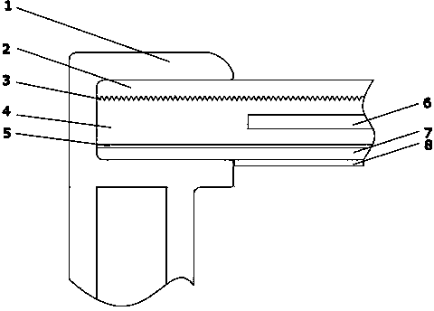
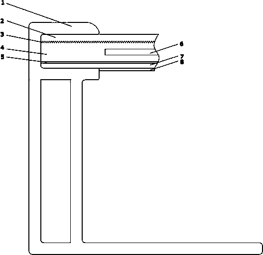
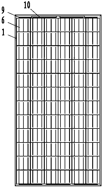
[0018] The new photovoltaic module involved in the present invention includes a junction box and a laminate, and is characterized in that: the laminated structure includes functions of absorbing infrared and ultraviolet light or other wavelengths of light or reflecting infrared light with a thickness of 2mm from top to bottom. The front panel with the function of ultraviolet light or other wavelengths of light is rolled tempered glass 2, the PVB encapsulation layer with UV absorption or transmission function 4, crystalline silicon battery (single crystal, polycrystalline, similar to single crystal battery) 6, 2mm thick The inner surface of the backboard float tempered glass substrate 7 coated with a highly reflective ceramic film, the backlight surface of the front glass substrate 2 is provided with a textured suede surface 3, and the inner surface of the backplane glass substrate 7 is coated with a high reflective ceramic film 5, The outer surface of the backplane glass substr...


PUM

PropertyMeasurementUnit
thicknessaaaaaaaaaa

Abstract

The invention discloses a photovoltaic module applied to new technologies. The photovoltaic module comprises a junction box and a lamination layer, wherein the lamination layer sequentially comprises the following components from top to bottom: a front plate tempered glass matrix capable of absorbing or reflecting infrared light and ultraviolet light or light with other wavebands, a front plate tempered glass textured suede, a packaging layer with an UV (ultraviolet) absorption or transmission function, a back plate tempered glass matrix, and a heat dissipation film layer; a crystalline silicon battery is arranged in the packaging layer, and a reflective function film layer is plated on the inner surface of the back plate tempered glass; an aluminium alloy border is installed at the periphery of the lamination layer composed of the layers above. The photovoltaic module disclosed by the invention is reasonable in structure; the internal temperature of the module can be effectively reduced, the output power of the module can be increased, and the service life of the module can be prolonged.

Description

technical field [0001] The invention relates to a backplane technology applied to a photovoltaic module, in particular to a brand-new improvement to the conventional crystalline silicon photovoltaic module, and belongs to the field of photovoltaic technology. Background technique [0002] Photovoltaic modules are the core components of photovoltaic power generation applications. According to the inventor's understanding, the front glass of the double-glass photovoltaic module produced industrially at home and abroad does not have the excellent characteristics of absorbing or reflecting infrared light or ultraviolet light, which will cause the temperature inside the module to rise, thereby resulting in the output power of the module and The service life is reduced, and the back glass is transparent or translucent, which will directly transmit the light from the back plate, so that the battery cannot fully absorb and utilize the reflected light of the back glass, thereby affec...

Claims


Application Information

Patent Timeline
Patent Type & Authority Applications(China)
IPC IPC(8): H01L31/048H01L31/052
CPCY02E10/52H01L31/042Y02E10/50H01L31/048H01L31/02366B32B17/10036B32B17/10091B32B17/10174B32B17/10678B32B17/10788F24S25/20H01L31/0488Y02E10/47
Inventor 杨向华高元准薛松华龚佳琳
Owner HANWHA SOLARONE QIDONG
Learn More