Rocket propulsion enhancing design

A technology of rocket propulsion and rocket thrust, applied in the direction of self-propelled bombs, offensive equipment, projectiles, etc.

Inactive Publication Date: 2007-10-17
施仲伟
View PDF0 Cites 7 Cited by
  • Summary
  • Abstract
  • Description
  • Claims
  • Application Information

AI Technical Summary

Problems solved by technology

[0003] High explosives cannot be used for thrust on the ground because it

Method used


Image

  • Rocket propulsion enhancing design
  • Rocket propulsion enhancing design
  • Rocket propulsion enhancing design

Examples


Embodiment Construction

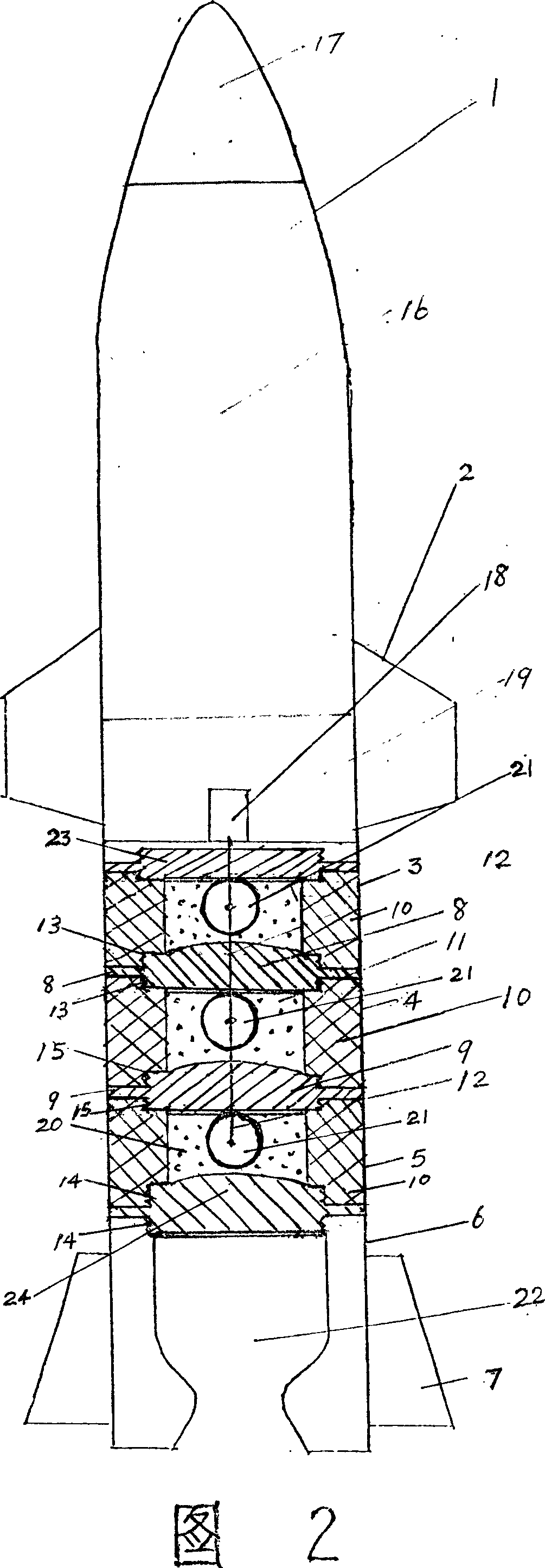
[0057] When the novel thrust rocket of the present invention needs to be launched, the conventional thrust powder (2) in the conventional thrust powder initial booster (6) of the last stage is ignited earlier and the rocket is sent to a space above 300m, and then the time difference firing device at the warhead bottom ( 18) The firing wire (12) sends sparks to detonate through the time difference, and the spherical explosive (21) in the first cartridge (5) detonates in the cartridge (5), and the detonation wave pushes away downward and to the surrounding force " Conventional thrust gunpowder initial booster (6) "and the screw connection (slip) between the cartridge ring (10) and its upper top plate (9), the detonation wave axis thrust upwards at that time (through a certain cylinder wall After the effect is strengthened) the high-strength pushes the thicker top plate (9) of the entire rocket to advance the front part of the rocket, and the top (bottom) plates 23, 8, 9, and 24 s...


PUM


Abstract

The invention relates to a method for increasing rocket impellent which provides module combined multi-section ''high explosive cartridge'' to launch the rocket for increasing rocket launch speed and shot. The invention first uses ''conventional impellent gunpowder initial propelling booster'' to send bullet and the cartridge to high altitude more than 300 m, time difference percussion mechanism at bullet bottom detonates the high explosive in cartridge one by one in predetermined time difference, and then the high explosive detonates in high altitude, so that it can safely provides impellent greatly large than any solid or liquid propellant, therefore the rocket can fly very far distance, coupling with guide apparatus, to correctly get to object. The invention can be used for rigid body launch in military and space navigation.

Description

1. Technical field: [0001] The invention relates to a design for enhancing the propulsion of a rocket, which can substantially increase the speed and range of the rocket, has a simple structure, is convenient to operate, greatly reduces weight and fuel consumption, and belongs to the field of rocket propulsion. 2. Background technology: [0002] Rockets are widely used, but most of them are used in the military. In a conventional sense, rockets can be divided into two types: "self-propellant" type and external propulsion source, according to its principle and the energy source for propulsion during launch. The former propeller is inside the rocket, which generates a very high speed by releasing highly compressed gas to push the rocket forward. Since the propellant can only provide a fairly limited acceleration process for the rocket, the striking distance is quite limited; the latter rocket It is propelled by an external launch device. This device is also propelled by highly...

Claims


Application Information

Patent Timeline
IPC IPC(8): F42B15/00
Inventor 施仲伟
Owner 施仲伟
Why Eureka
Try Eureka