Method and device for thread distribution in a warping frame

A technology of rotating axis and yarn group, applied in the direction of transportation and packaging, other manufacturing equipment/tools, textiles and papermaking, etc., can solve problems such as delaying processing operations, and achieve the effect of speeding up the working process

Active Publication Date: 2007-10-17
KARL MAYER STOLL R&D GMBH
View PDF0 Cites 7 Cited by
  • Summary
  • Abstract
  • Description
  • Claims
  • Application Information

AI Technical Summary

Problems solved by technology

However, every adjustment of the ribbon composition in terms of yarn type, yarn sequence or wound ribbon width requires a stoppage, which significantly delays the processing operation

Method used


Image

  • Method and device for thread distribution in a warping frame
  • Method and device for thread distribution in a warping frame
  • Method and device for thread distribution in a warping frame

Examples


Embodiment Construction

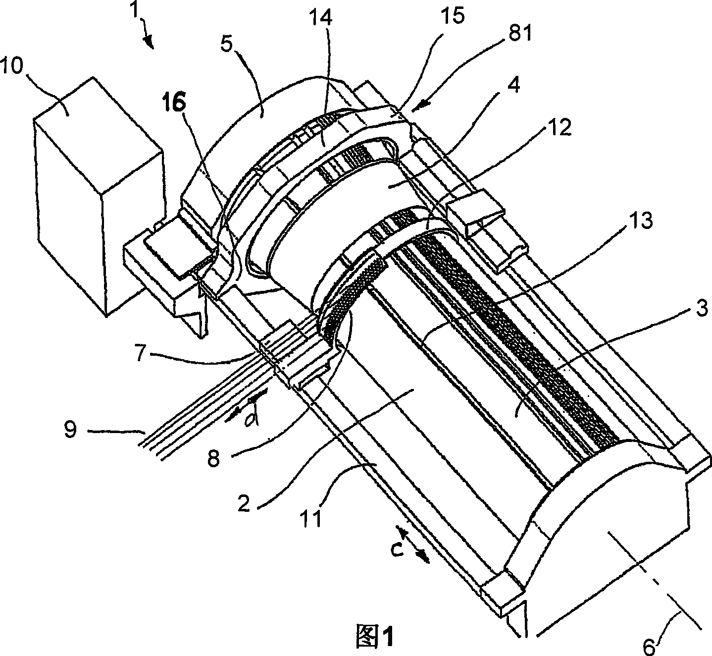
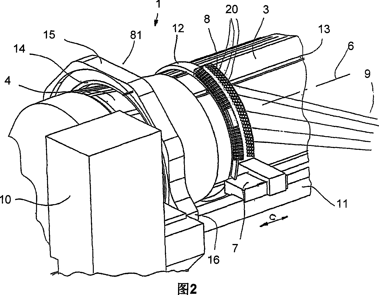
[0050] As shown in FIGS. 1 and 2 , the warping machine, generally designated 1 , consists essentially of a warping cylinder 2 as a winding body, which has a cylindrical section 3 and a conical section 4 . The warping cylinder is supported rotatably about a winding body axis or cylinder axis 6 in a frame 5 . The warping table 7 stands still on the guide mechanism 11 of the warping table, and the warping table can move in the arrow direction c parallel to the rotation axis 6 on the guide mechanism 11 . A yarn selection device 8 is provided on the warping table 7, and the yarn selection device can move relative to the warping cylinder in a direction perpendicular to the rotation axis of the warping cylinder (ie, arrow direction d).

[0051] The yarn selection device 8 itself surrounds the surface of the warping cylinder 2 in an arc of eg 90°. A plurality of thread guide modules 20 , which are only schematically represented here, are arranged on the thread selection device in a m...


PUM


Abstract

The invention relates to a method for winding a strip (17) consisting of a plurality of parallel threads (18) onto a rotating warping drum (2), wherein the winding position of each individual thread is determined with the aid of a thread guide (21) which is associated with a thread selection device (8) and which is allocated to said thread. The thread guides (21) are displaced in the direction of the axis of rotation (6) of the warping drum (2) from a rest position into a working position and the individual threads (18) are seized successively by an internal thread carrier (30) associated with the warping drum (2).

Description

technical field [0001] The invention relates to a method and a device for winding a strip of parallel yarns onto a winding body rotating about an axis of rotation. In textile technology, for example, such methods and devices are used in weaving preparation for warping weaving warp threads. However, winding operations are also required in other fields, for example in the wire industry. Therefore, the invention is also not limited to textile application purposes, the term "yarn" includes any elongated windable element, regardless of cross-sectional shape or material. Background technique [0002] One requirement of modern warping methods is, for example, that high speeds must be performed, whereby a change in the composition of each wound strip is to be ensured. This requirement is made especially for the so-called sutras or short sutras. However, whenever an adjustment of the strip composition is made with respect to the type of yarn, the sequence of the threads or the wid...

Claims


Application Information

Patent Timeline
Patent Type & Authority Applications(China)
IPC IPC(8): D02H13/18D02H3/00B65H57/16
CPCD02H13/18D02H3/00D02H3/02D02H9/00
Inventor R・斯托琛恩格L・孔兹
Owner KARL MAYER STOLL R&D GMBH
Why Eureka
Try Eureka