Conductor rail and manufacturing method thereof

A technology of conductive rails and brushes, which is applied in the direction of power rails, etc., can solve the problems of high manufacturing cost and high forming requirements of brush plates, and achieve the effects of less corrosion, easy deformation, and reasonable deformation

Active Publication Date: 2007-10-24
HUNAN HUAPIN RAIL TRANSIT CO LTD
View PDF2 Cites 3 Cited by
  • Summary
  • Abstract
  • Description
  • Claims
  • Application Information

AI Technical Summary

Problems solved by technology

[0005] However, the conductive rail of this invention needs to be equipped with rollers on the back and both sides of the base body during assembly, and the metal material of the base body is deformed and filled in the depressions of the slats on the back of the brush surface under the pressure of the rollers, and for better filling effect It is necessary to replace the roller on the back of the base body so that the metal material of the base body can be more fully deformed and filled in the dimples of the slats on the back of the brush face; due to the limitation of metal deformation, the slats on the back of the brush face need to have a certain height , the forming requirements are relatively high in the manufacturing process; and due to the limitation of the assembly method, it is difficult to completely fill the recesses of the back strips of the brush surface after deformation of the base metal; the brush plate manufacturing cost of this assembly method is relatively high

Method used


Image

  • Conductor rail and manufacturing method thereof
  • Conductor rail and manufacturing method thereof
  • Conductor rail and manufacturing method thereof

Examples


Embodiment Construction

[0024] The present invention will be further described below in conjunction with the accompanying drawings and embodiments.

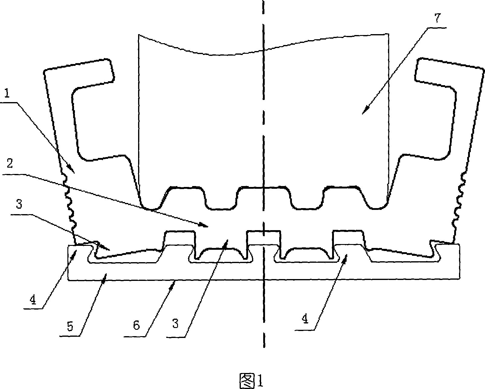
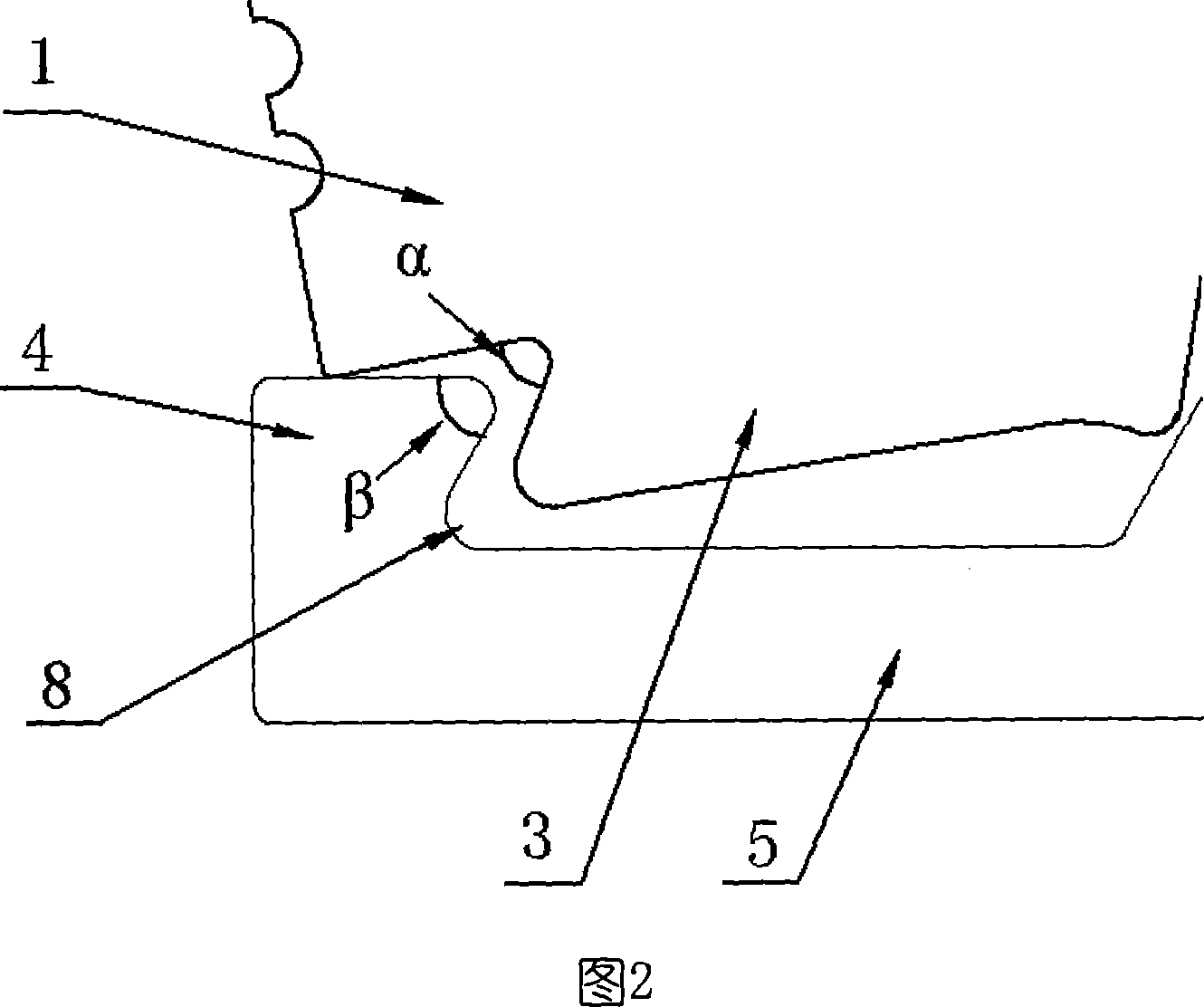
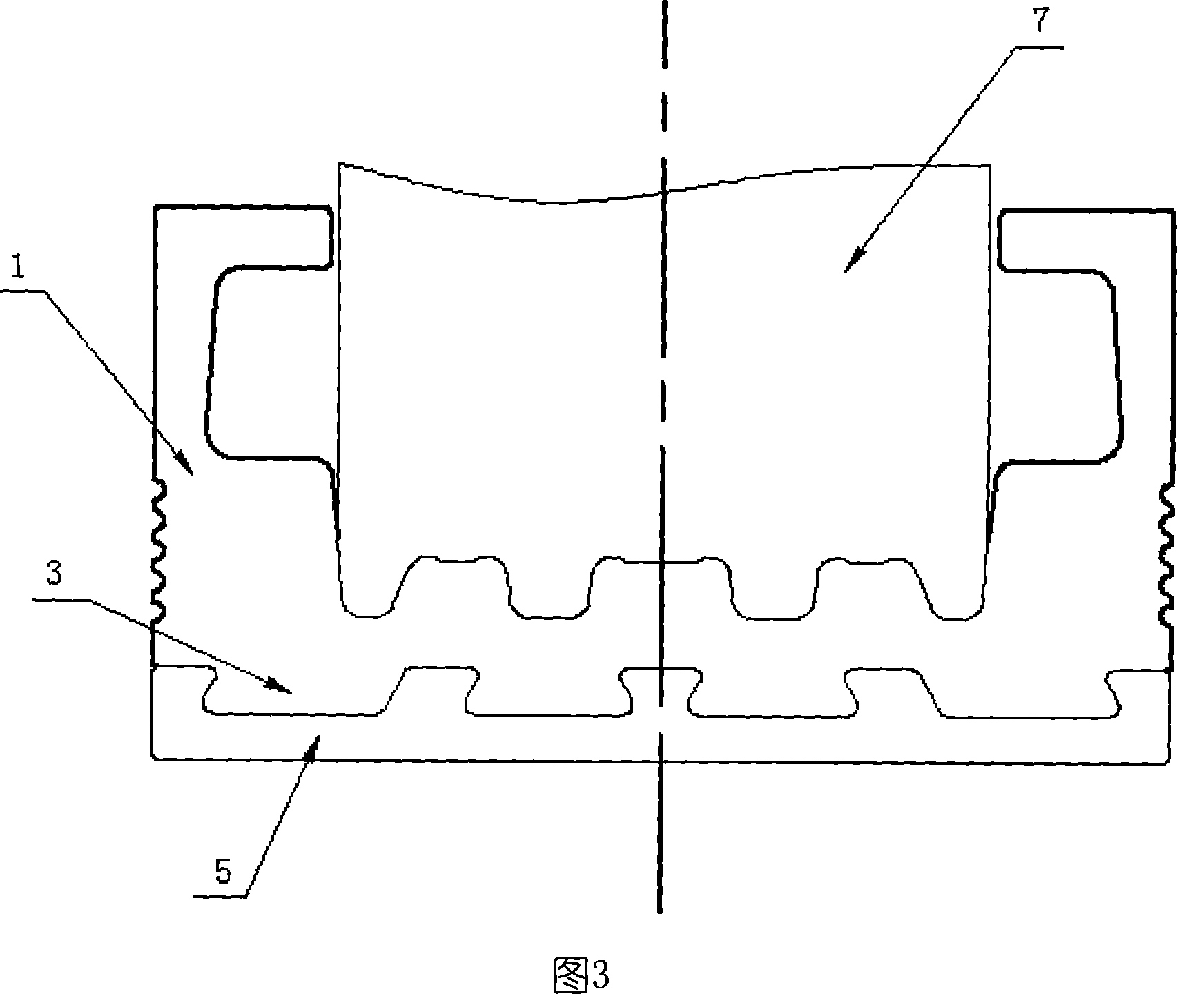
[0025] Specific embodiment 1 of the present invention, as shown in Fig. 1, 3, a kind of conductive rail, comprises the electric brush surface 5 that matrix 1 and wear-resistant material are made, and the back of electric brush surface 5 has protruding slat 4 inlay In the base body 1 , the portion between the strip 4 and the back of the brush face 5 forms a recess 8 , which is filled with the material of the base body 1 .

[0026] As shown in Figure 1, the interlaced filling part of the matrix 1 and the slats 4 is located between the two outermost slats 4 on the back of the brush surface 5; before assembly, the bottom of the filling part 3 of the matrix 1 is sunken upwards, and A space is formed between the backs of the brush faces 5 , and after the assembly is completed, the space is squeezed and disappears, and the bottom of the filling part 3 of the b...


PUM


Abstract

The invention relates to a conductive rail that comprises the base and abrasion resistant material made electric brush surface with protruding batten embedded inside the base, at least one batten and electric brush surface and the back formed into pits, which is stuffed with base material. It features in partial bending of the assembly part of the front base, through at least one time deformation assembly to straighten it up and stuffing it between the battens. It is close in adhesion, firm, convenient in base and electric brush assembly, low in production cost.

Description

technical field [0001] The invention relates to a conductive rail and a manufacturing method thereof. The conductive rail is mainly used for electric railway system and electric current transmission of overhead transmission equipment. Background technique [0002] Existing conductor rails are usually assembled from a base body and a brush face made of wear-resistant metal. In practical applications, the collector shoe matched with the conductive rail is fixed on the locomotive, and a certain contact pressure needs to be maintained between the collector shoe and the brush surface during the operation of the locomotive to ensure current transmission. Among them, the matrix is ​​the main current carrier, which is used to conduct current along the extension direction of the guide rail, and bear the self-weight and compression load of the collector shoe; the brush surface is used to bear the wear caused by the high-speed friction of the collector shoe, and transfer the The curre...

Claims


Application Information

Patent Timeline
Patent Type & Authority Applications(China)
IPC IPC(8): B60M1/30
Inventor 曾鉴
Owner HUNAN HUAPIN RAIL TRANSIT CO LTD
Why Eureka
Try Eureka