
Silicon oil fan clutch

A clutch and fan technology, applied in the direction of clutches, fluid clutches, machines/engines, etc., can solve the problems of affecting the transmission torque, large cutting resistance, cutting deformation, etc.

Inactive Publication Date: 2007-10-24
五龙控股有限公司
View PDF0 Cites 3 Cited by
  • Summary
  • Abstract
  • Description
  • Claims
  • Application Information

AI Technical Summary

Problems solved by technology

Since the forming of the rectangular circular groove is completed by the forming turning tool, it is cut with a three-sided cutter, so the cutting resistance is large during the processing, and the vibration generated by cutting is large, which affects the machining accuracy, and the width of the rectangular circular groove is consistent from top to bottom. Easy to produce cutting deformation
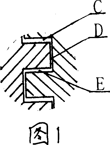
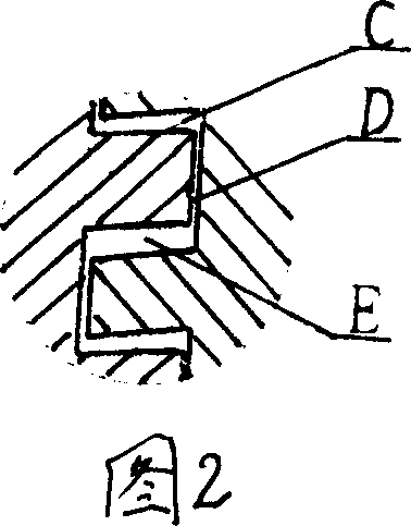
In this way, in order to ensure the assembly, the gap of the labyrinth groove is increased, and at the same time, the gap size of the labyrinth groove at different positions is uneven (see Figure 2), which affects the transmission torque and reduces the transmission torque.
In order to ensure the strength and reduce deformation of the rectangular ring groove, the width of the labyrinth groove must be increased accordingly, so that the number of labyrinth grooves is correspondingly reduced, and the filling area of ​​silicone oil is also correspondingly reduced, so the transmitted torque is also limited to a certain extent

Method used


Image

  • Silicon oil fan clutch
  • Silicon oil fan clutch
  • Silicon oil fan clutch

Examples


Embodiment Construction

[0009] The present invention will be further described below in conjunction with the embodiments and accompanying drawings.

[0010] This embodiment is an electronically controlled silicone oil fan clutch.

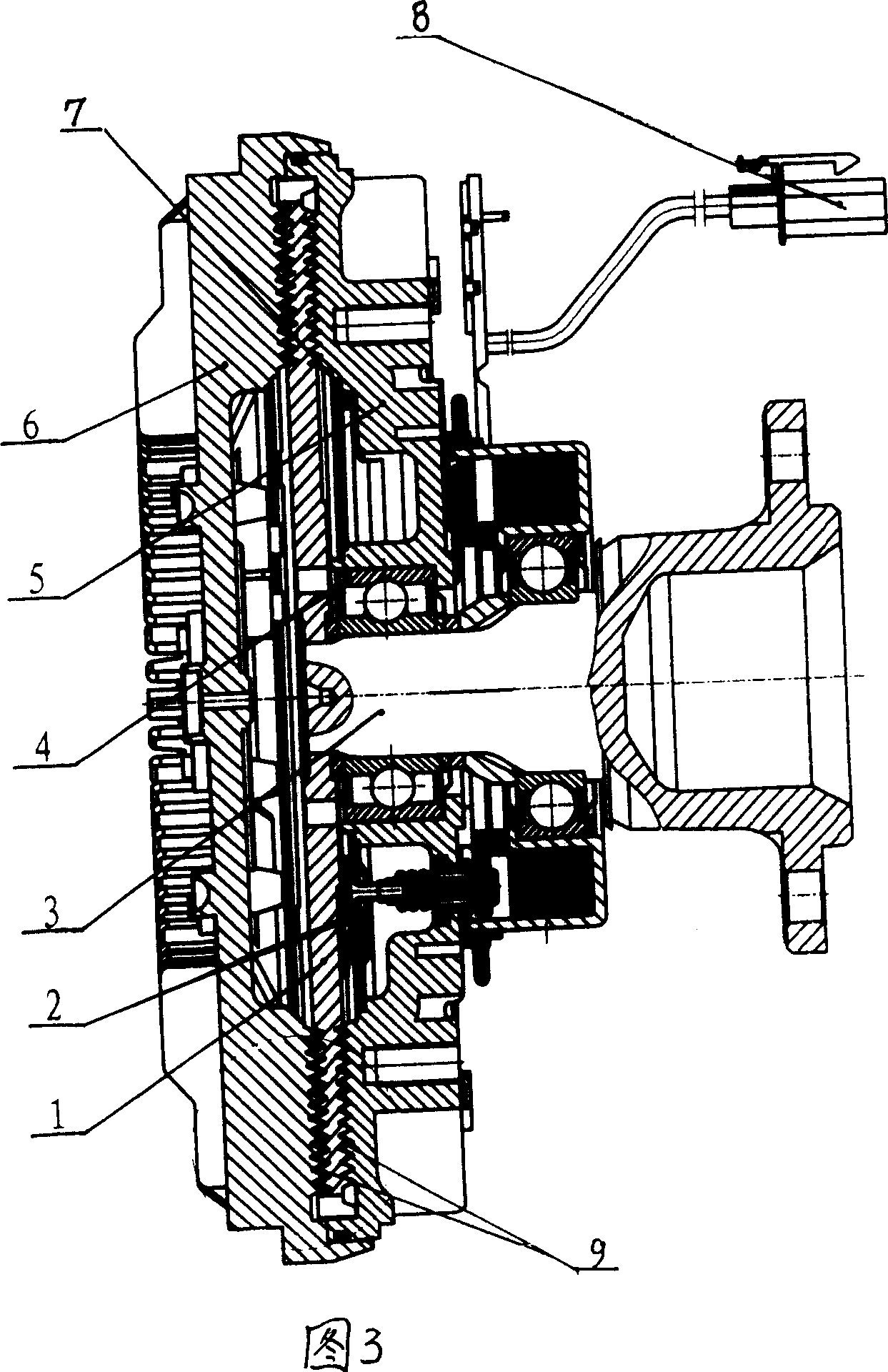
[0011] Referring to Fig. 3, a silicon oil fan clutch includes a driving disc 1, a driving shaft 2, a bearing 3, a rear cover 4, a front cover 5, a partition 6, a valve plate 7, a labyrinth groove between the front cover 5 and the driving disc 1 9 is a double-sided multi-ring triangular labyrinth groove.


PUM


Abstract

A silicone oil fan clutch used in vehicles engine fan cooling system includes active disk, active axle, bearings, rear cover, fore cover, baffles and valve block, the labyrinth groove between the fore cover and the active axle is double-surface multi-ring triangular labyrinth groove. It greatly increases the capability of transmitting torque.

Description

1. Technical field [0001] The invention relates to a silicone oil fan clutch used in a fan cooling system of an automobile engine. 2. Background technology [0002] Silicon oil fan clutch is an energy-saving and environmental protection product used in the fan cooling system of automobile engine. The driving shaft and the driving disk are integrated into an input end, and the rear cover or front cover is connected with the fan to become an output end. The working medium is silicone oil, and the torque is transmitted by using the silicone oil to enter the labyrinth groove gap between the front cover and the driving disc to generate friction. [0003] At present, the labyrinth groove between the front cover and the driving disc is shown in Figure 1, which is a multi-ring rectangular circular groove. As shown in Figure 1, the torque is transmitted by the silicone oil medium entering the C, E, and D gaps. From the structure point of view, the torque t...

Claims


Application Information

Patent Timeline
IPC IPC(8): F16D35/00F01P5/04
Inventor 丁维福刘正耀王应刚
Owner 五龙控股有限公司
Learn More