Ball valve

A ball valve and valve cavity technology, applied in the field of valves with spherical valve elements, can solve problems such as large pressure loss, affecting the mass flow of saturated water in the pipeline, and difficult maintenance.

Inactive Publication Date: 2007-10-24
LANZHOU UNIVERSITY OF TECHNOLOGY
View PDF0 Cites 7 Cited by
  • Summary
  • Abstract
  • Description
  • Claims
  • Application Information

AI Technical Summary

Problems solved by technology

This situation not only affects the mass flow rate of saturated water in the pipeline, but also the cavitation phenomenon caused by water vapor has an adverse effect on both the pipeline and the valve
In high-demand working conditions, the valve core...

Method used


Image

  • Ball valve
  • Ball valve

Examples


Embodiment Construction

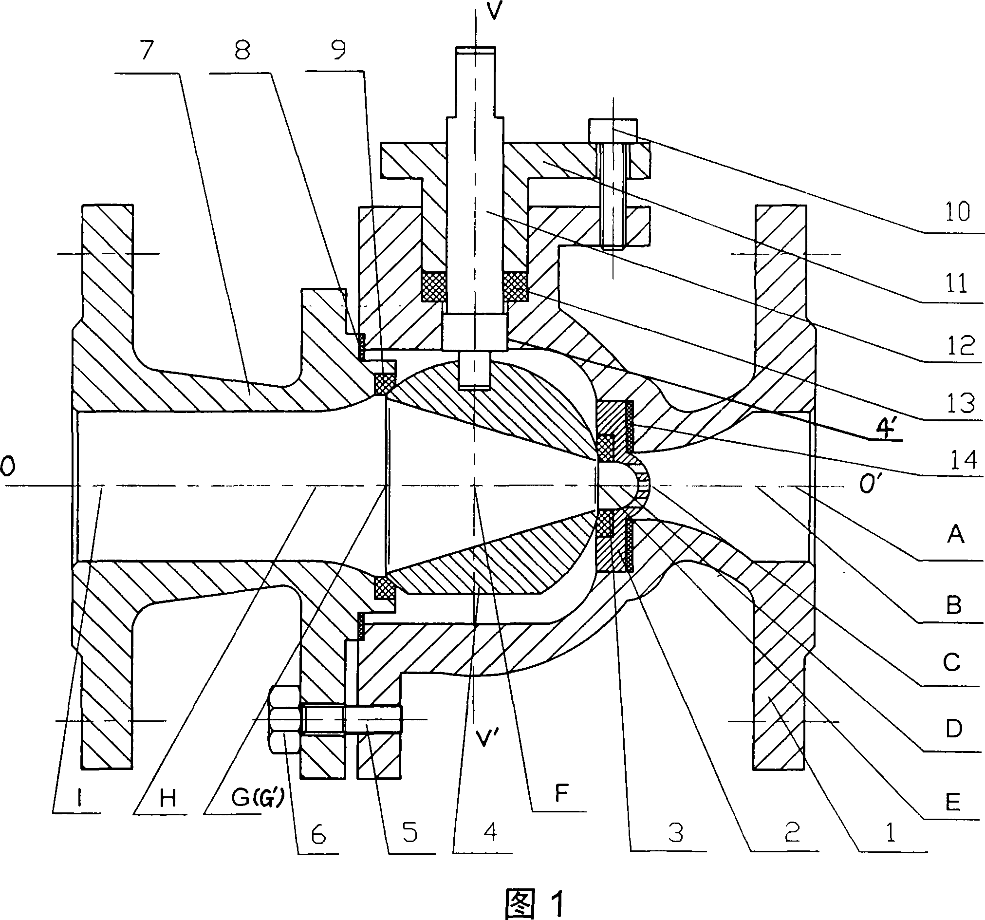
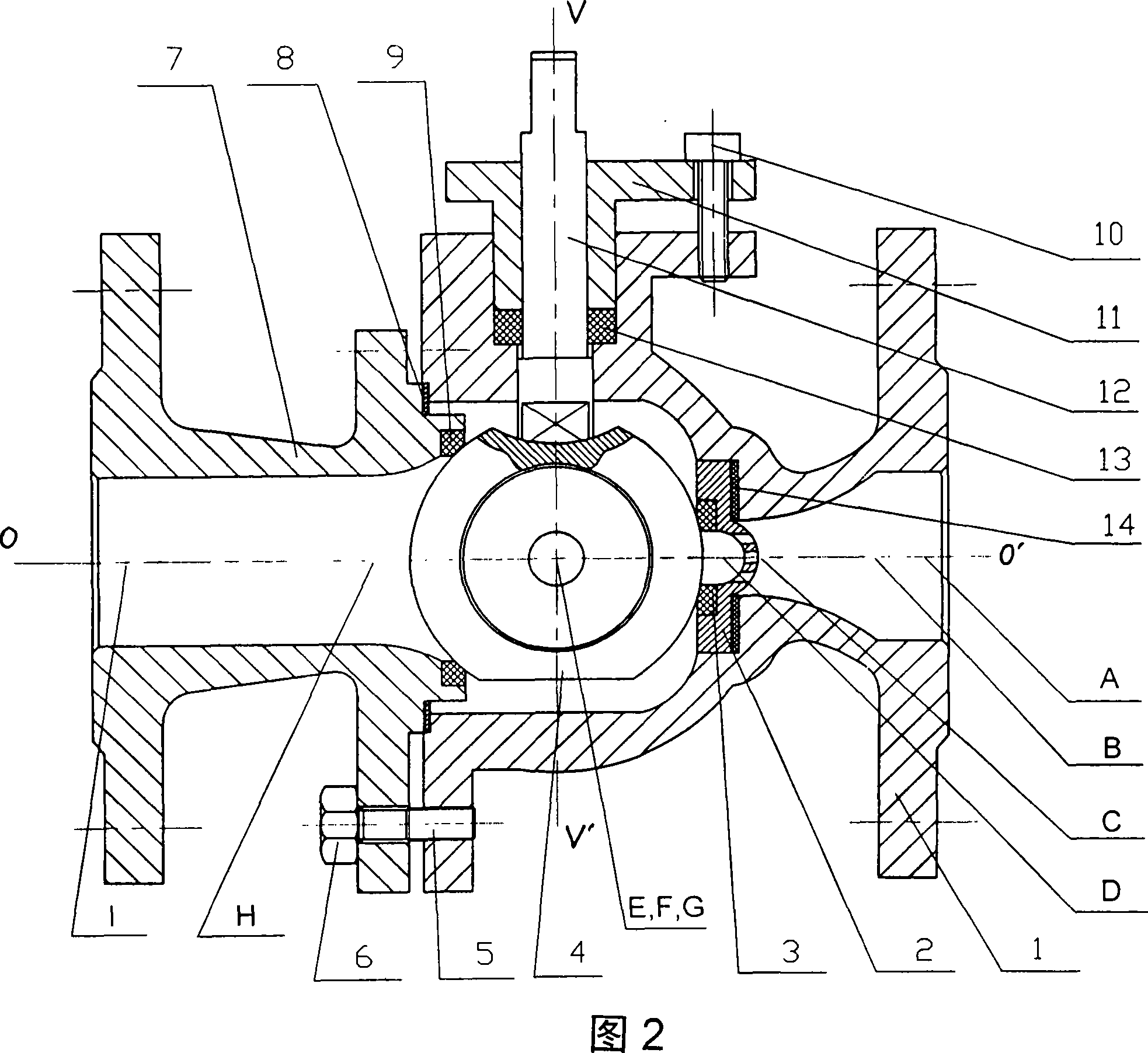
[0008] As shown in Figure 1, the inner surface of the valve cavity of the left valve body 7 from the inlet I of the valve cavity of the left valve body 7 to the starting point H of left diffusion is a cylindrical surface. The valve cavity of the valve body 7 is a conical surface, the left diffuser starting point H is the intersection of the geometric circular plane and the valve cavity axis OO' at the intersection of the conical surface and the cylindrical surface, and the left diffuser end point G is the intersection of the conical surface and the sphere 4 The intersection point of the geometric circular plane and the axis OO' of the valve cavity. Point F is the intersection of the center line VV' of the sphere 4 and the axis OO' of the valve cavity. Point E is the intersection of the geometric circular plane at the intersection of the right valve body 1 and the sphere 4 and the axis OO' of the valve chamber. The valve cavity of the right valve body 1 from the right diffuser...


PUM


Abstract

A ball valve aims at achieving the stable regulation flow in ball valve regulating saturated water process, reducing the generating of phase transition and playing a role of anti-air cavity and reversing anti-negative waterhammer. The left valve body valve seat 9 is installed between the left valve body 7 and the ball body 4, the ball body 4 is opened with a conical through-hole through the valve cavity axial cord, the ball body 4 is installed in the inner cavity of right valve body, the upper end of the ball body 4 is opened with key groove 4'along the central line of ball body 4, the lower end of the valve bar 12 is installed in the key groove 4'and drives the ball body 4 rotating around the central line of ball body 4 as axial cord; the diffuser part of valve cavity of left valve body 7 starts with the left diffuser start point H and finishes with the left diffuser finishing point G, the inner surface of left valve body 7 valve cavity from the valve cavity input mouth I to the left diffuser start point H, the valve cavity of left valve body 7 is a conical surface from the left diffuser start point H to the left diffuser finishing point G, the valve cavity of right valve body 1 is conical surface from the right diffuser start point D to the right diffuser finishing point B, the valve cavity between the right diffuser finishing point B and the valve cavity mouth A of right valve body 1 is circular column surface.

Description

technical field [0001] The invention relates to a valve, in particular to a valve with a spherical valve element. Background technique [0002] In the prior art, when saturated water is transported in large industrial pipelines, due to the throttling effect of the valve, the pressure of the saturated water drops below the saturation pressure when passing through the valve, which causes a phase change of part of the saturated water and generates water vapor . Not only does this condition affect the mass flow rate of saturated water in the pipeline, but the cavitation caused by the water vapor has an adverse effect on both the pipeline and the valves. In high-demand working conditions, the valve core with additional tortuous passages is generally used to slow down the flow rate, slow down the amount of water vapor generated and resist cavitation, which not only causes a large pressure loss, but also has a complicated structure and is difficult to maintain. Contents of the i...

Claims


Application Information

Patent Timeline
IPC IPC(8): F16K5/06F16K5/08F16K27/06
Inventor 余龙俞树荣
Owner LANZHOU UNIVERSITY OF TECHNOLOGY
Why Eureka
Try Eureka