Activation based zero power consumption standby power control device

A power control device, zero-power standby technology, applied in the direction of circuit devices, battery circuit devices, electrical program control, etc., can solve the problems of increased cost and system complexity, increased battery inrush current, and short start-up time, etc., to achieve guaranteed Long standby life, guaranteed standby safety, and improved operational safety

Inactive Publication Date: 2007-10-24
周先谱
View PDF1 Cites 13 Cited by
  • Summary
  • Abstract
  • Description
  • Claims
  • Application Information

AI Technical Summary

Problems solved by technology

[0006] 1) It is difficult to reduce standby energy consumption;
[0007] 2) There are potential safety hazards in standby
[0011] 3) Only the device and its power supply generate standby energy
The general problems of these solutions are: higher complexity, more cost increase and various problems in the special application environment of home appliances
[0018] 1) The battery and additional circuits may significantly increase the cost;
[0019] 2) It is necessary to ensure that the controlled electrical appliance is started before the end of the battery discharge cycle, otherwise the controlled device will not be able to start after the battery is discharged, and other remedial measures will increase the complexity of the operation
[0020] 3) It needs to be activated after long-term storage, which increases the complexity of the control circuit
[0021] 4) It cannot provide a life span that matches the controlled electrical appliance
[0027] 1) The controller needs to go through the power-on reset process to start, this process is much longer than the sleep wake-up time, which may be very difficult for the detection of non-repetitive infrared codes; at the same time, the standby (sleep) and pin leakage current of modern single-chip microcomputers Very small, the battery energy loss caused by this factor is actually so small that it can be ignored, and the complexity of the self-shutdown technology is relatively large;
[0028] 2) The starting current of the control system, especially the starting current of the intermediate relay, must all come from the power supply of the battery itself, which increases the impact current on the battery, which is extremely unfavorable to the life of the battery itself and power consumption;
[0029] 3) Many electrical appliances, especially low-end electrical appliances, have low power supply and short start-up time. The same purpose of using AC power supply monitoring can be achieved only by monitoring the working status of the controlled equipment, but the detection time lags a little, so The resulting energy loss is acceptable
Therefore, the mere need to monitor AC power for this purpose is insufficient in many cases and adds cost and system complexity

Method used


Image

  • Activation based zero power consumption standby power control device
  • Activation based zero power consumption standby power control device
  • Activation based zero power consumption standby power control device

Examples


Embodiment Construction

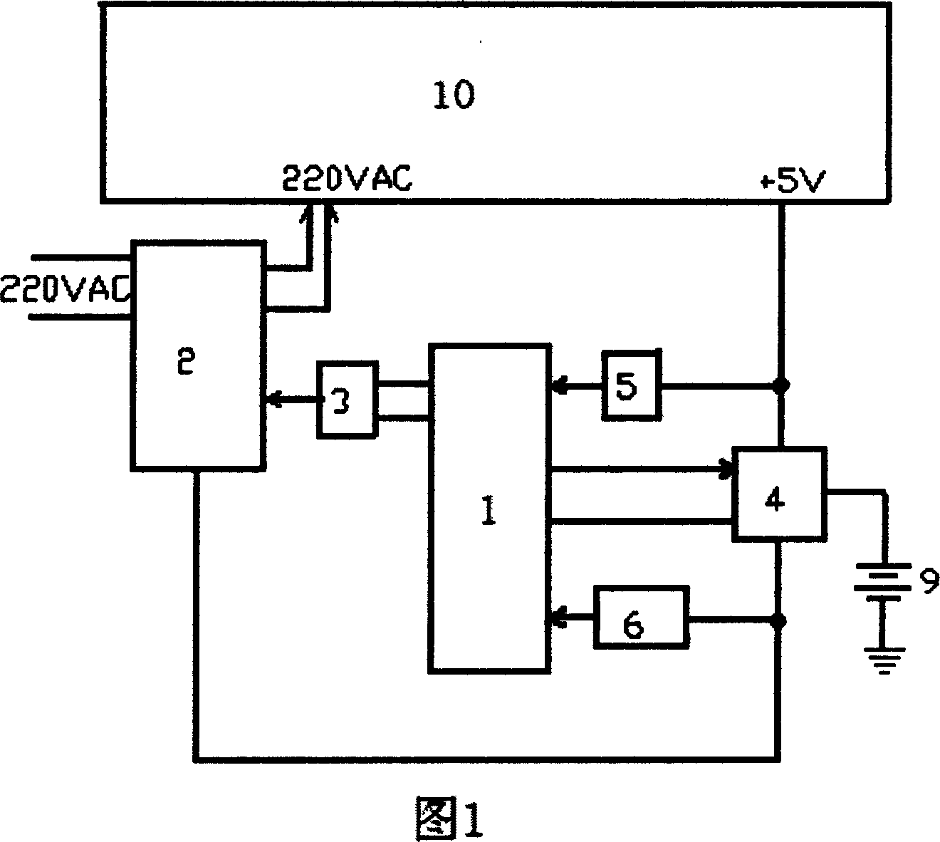
[0055] As shown in Figure 1, the zero-power standby power control device based on activation of the present invention includes a controller 1, an AC power control switch 2, a driver 3, a power switching circuit 4, a controlled device state monitoring circuit 5, a signal sensing circuit 6 and battery 9; wherein,

[0056] The controller 1 is connected to the AC power control switch 2 through the driver 3 , and the AC power control switch 2 is connected to the mains AC power on the one hand and connected to the controlled device 10 through an internal normally open contact. The two input terminals of the power switching circuit 4 are respectively connected to the working power of the controlled device and the battery 9, and the control terminal is connected to the controller 1, and the output of the power switching circuit 4 is used as the zero work based on activation. The working power of the standby power consumption control device is respectively connected to the controller 1...


PUM


Abstract

The invention discloses a zero consumption wait power controller based on activation, comprising a controller, a driver, a power switch circuit, an object device state detect circuit, a signal sensing circuit and a battery. When the signal sensing circuit receives a control signal, the controller is activated to receive a control signal from the signal sensing circuit, and the driver connects an alternative-current power supply of the object device via an alternative-current power control switch. And when the object device is in working, the controller according to received close code uses the driver to close the alternative-current power supply of the object device via the alternative-current power control switch, while the controller is in low consumption wait state, only the signal sensing circuit with low energy consumption works, to detect the signal change of the condition, thereby realizing low energy consumption and waiting safely.

Description

Technical field [0001] The invention relates to the field of household appliances, in particular to an activation-based zero-power standby power control device for household appliances. Background technique [0002] Household appliances usually use mains power as the working and standby power supply. The specific power supply methods of the standby circuit are divided into two types: [0003] 1) Use the normal working power supply of the equipment as the standby power supply; [0004] 2) Use an independent auxiliary AC power supply as the standby power supply; [0005] There are two problems with this traditional standby power supply model: [0006] 1) It is difficult to reduce standby power consumption; [0007] 2) There are potential safety hazards in standby mode. [0008] Non-AC power standby provides the possibility to overcome the above disadvantages at the same time. The basic idea is: [0009] 1) Utilize an independent standby power control device to control the...

Claims


Application Information

Patent Timeline
IPC IPC(8): G05B19/05H02J7/00G08C23/04
Inventor 周先谱
Owner 周先谱
Why Eureka
Try Eureka