A pulse width adjustable laser

A laser and pulse width technology, applied in lasers, laser parts, phonon exciters, etc., can solve the problems of high cost, large loss, energy waste, etc., and achieve the effect of easy installation and debugging, and easy engineering promotion

Inactive Publication Date: 2007-10-24
BEIJING GK LASER TECH
View PDF1 Cites 21 Cited by
  • Summary
  • Abstract
  • Description
  • Claims
  • Application Information

AI Technical Summary

Problems solved by technology

[0006] The purpose of the present invention is to overcome the shortcomings of high cost, large loss, and serious energy waste in the prior art of using a Q-switched laser...

Method used


Image

  • A pulse width adjustable laser
  • A pulse width adjustable laser
  • A pulse width adjustable laser

Examples


Embodiment 1

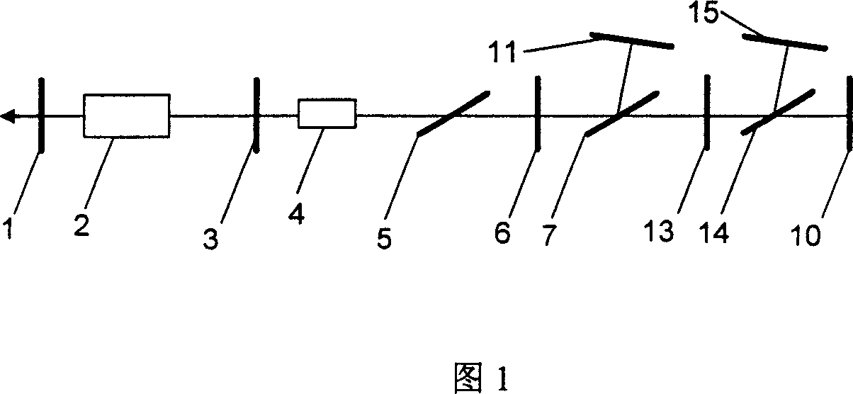
[0032] Referring to Figure 1, an electro-optic Q-switched pulse-width tunable laser is produced, including an output mirror 1, a laser rod 2, a quarter wave plate 3, a boosted electro-optic Q-switched Pockels cell 4, a first polarizer 5, and a first polarizer. A 1 / 2 wave plate 6, a second polarizer 7, a third 1 / 2 wave plate 13, a fourth polarizer 14, a first total mirror 10, a second total mirror 11, and a third total mirror 15. A second total-reflection mirror 11 is provided on one side of the polarizing plate 7, and the second total-reflection mirror 11 is used to reflect all the laser light reflected by the polarizing plate 7 back along the original path; the 1 / 2 wave plate is Movable, able to be removed or inserted into the optical path. The plane of the 1 / 2 wave plate is perpendicular to the laser light path. The polarization directions of all the polarizers are parallel, and the optical axis of all the 1 / 2 wave plates forms an angle of 45° with the polarization direction of ...

Embodiment 2

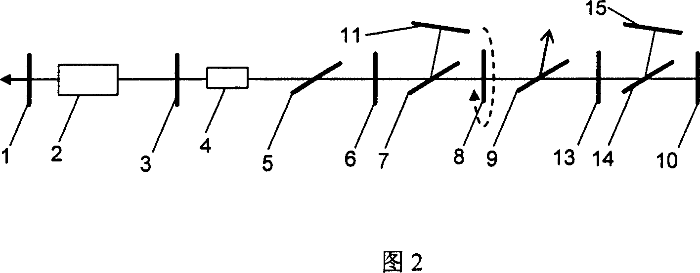
[0036] As shown in Fig. 2, a set of 1 / 2 wave plate 8 and polarizer 9 are inserted into the resonant cavity, and the 1 / 2 wave plate 8 can be rotated. When the light pulse oscillates in the resonant cavity determined by the mirror 15 or 11, by rotating the 1 / 2 wave plate 8, a certain range of pulse width adjustment can be achieved. The rotation of the 1 / 2 wave plate 8 can be achieved manually or electrically, which is easy for those skilled in the art to do. Others are the same as in Example 1.

Embodiment 3

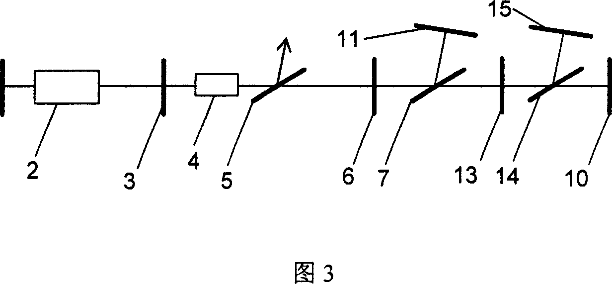
[0038] Embodiments 1 and 2 both use boost type electro-optic Q-switched Pockels cell 4, if a step-down type is used, the quarter-wave plate 3 in embodiment 2 needs to be removed. Others are the same as in Example 2.


PUM


Abstract

The disclosed laser with adjustable Q pulse width comprises: an output mirror, a laser rod, a Pockel's box together with a first full deflection mirror coaxial arranged on a straight line, a first polaroid between the Pockel's box and first deflection mirror, at least one movable 1/2 glass filter and polaroid (7) between former first polaroid and the first deflection mirror, a second full reflection mirror (11) near the polaroid (7) to deflect all laser from (7) backwardly. This invention is simple and convenient, and can be used in different lasers.

Description

Technical field [0001] The invention relates to a laser device capable of realizing tunable laser Q-switching pulse width. Background technique [0002] With the rapid development of laser technology, laser technology plays an increasingly important role in various fields, from military to civilian use, from scientific research to teaching, from industry to agriculture and sideline industries. At the same time, in engineering applications, the requirements for laser reliability, engineering, stability, assemblability, versatility, and ease of operation are getting higher and higher. [0003] The existing single pulse width laser output can no longer meet the application requirements of customers in many occasions. The current scheme for realizing pulse-width tunable coordination is mainly realized by chopper switches outside the laser resonator. The tunable pulse-width scheme has several disadvantages: First, the scheme can only achieve the output pulse width of the original lase...

Claims


Application Information

Patent Timeline
IPC IPC(8): H01S3/08H01S3/10H01S3/105H01S3/00
Inventor 崔建丰樊仲维裴博薛岩
Owner BEIJING GK LASER TECH
Why Eureka
Try Eureka