Hybrid IC for ultrasound beamformer probe

A technology of ultrasonic probe and high-voltage integrated circuit, which is applied in sound-generating devices, re-radiation of sound waves, ultrasonic/sonic/infrasonic diagnosis, etc., and can solve the problems of bulky IC devices, energy consumption, and limited working voltage

Inactive Publication Date: 2007-10-24
KONINKLIJKE PHILIPS ELECTRONICS NV
View PDF2 Cites 7 Cited by
  • Summary
  • Abstract
  • Description
  • Claims
  • Application Information

AI Technical Summary

Problems solved by technology

IC devices that provide high voltage are bulky, consume more power, and thus generate more heat
However, providing high density IC devices limits the operating voltage

Method used


Image

  • Hybrid IC for ultrasound beamformer probe
  • Hybrid IC for ultrasound beamformer probe
  • Hybrid IC for ultrasound beamformer probe

Examples


Embodiment Construction

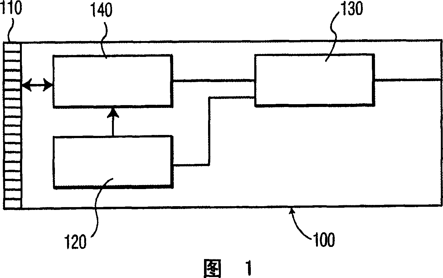
[0023] FIG. 1 is a block diagram of an ultrasound probe 100 including a transducer 110 . Transmit circuitry 120 is disposed within probe 100 to generate electrical pulses that are applied to transducer 110 to generate a transmit beam within the subject. Transmit circuitry 120 generates the electrical pulses in response to signals received from beamformer circuitry 130, which applies a time delay for focusing the transmit pulses as desired. Beamformer circuitry 130 is arranged to receive reflected pulses from transducer 110 . The beamformer circuit 130 may also apply a time delay and / or gain control to set the power level of the reflected beam. A transmit / receive (T / R) switch 120 is connected to transducer 110, transmit circuitry 120, and beamformer circuitry 130 for isolating transmitted pulses from reflected pulses. In a preferred embodiment, the ultrasound probe 100 is a microbeamformer ultrasound probe with thousands of transducers to enable three-dimensional imaging. Al...


PUM


Abstract

A hybrid integrated circuit package for a microbeamformer in an ultrasound probe includes a substrate, a driver circuit for generating transmit pulses to be transmitted to the transducer elements of the probe for producing a transmit beam, and a beamformer circuit including time delay circuits and a summation circuit, the time delay circuits being operatively arranged for receiving a plurality of reflected pulses from the transducer elements and delaying the reflected pulses and the summation circuit operatively arranged summing groups of the delayed reflected pulses for producing beamformed signals. The driver circuit is part of a high voltage integrated circuit device including said driver circuit. At least a portion of the beamformer circuit is part of a low voltage integrated circuit device, wherein the high voltage integrated circuit and the low voltage integrated circuit are mounted on the substrate.

Description

technical field [0001] The present invention relates to a hybrid integrated circuit (IC) for an ultrasound beamformer probe that simultaneously provides the high voltage requirements of the transducer element interface and the high density functional requirements of the control and beamforming functions. Background technique [0002] Medical ultrasound imaging systems are used for non-invasive real-time viewing of the internal structures of the human body. An ultrasound imaging system includes a transducer array for transmitting and receiving ultrasound pulses. Each transducer is a piezoelectric element. The transmit beamformer circuit applies electrical pulses to individual transducers within the transducer array in a specific timing sequence to generate a transmit beam. The transmitted beam is reflected by tissue structures with completely different acoustic properties. The reflected beam is converted by the receiving transducer into electrical pulses, which are convert...

Claims


Application Information

Patent Timeline
Patent Type & Authority Applications(China)
IPC IPC(8): G01S7/521G01S15/89G10K11/34
CPCG01S15/8915G01S7/5208G10K11/346G01S15/8927G01S7/523A61B8/546
Inventor S·施韦策S·施米德特M·巴茨
Owner KONINKLIJKE PHILIPS ELECTRONICS NV
Why Eureka
Try Eureka