Bearing assembly for a centrifuge

A bearing device, centrifuge technology, applied in centrifuges, engine seals, mechanical equipment and other directions, can solve problems such as cost waste, and achieve the effect of increasing service life

Inactive Publication Date: 2007-10-31
FERRUM
View PDF0 Cites 5 Cited by
  • Summary
  • Abstract
  • Description
  • Claims
  • Application Information

AI Technical Summary

Problems solved by technology

[0006] A problem that occurs with this prior art bearing arrangement is that the shaft is subjected to both torsional and bending strains
Therefore, the centrifuge remains in a non-productive non-working state for a long time, which leads to considerable cost waste

Method used


Image

  • Bearing assembly for a centrifuge
  • Bearing assembly for a centrifuge
  • Bearing assembly for a centrifuge

Examples


Embodiment Construction

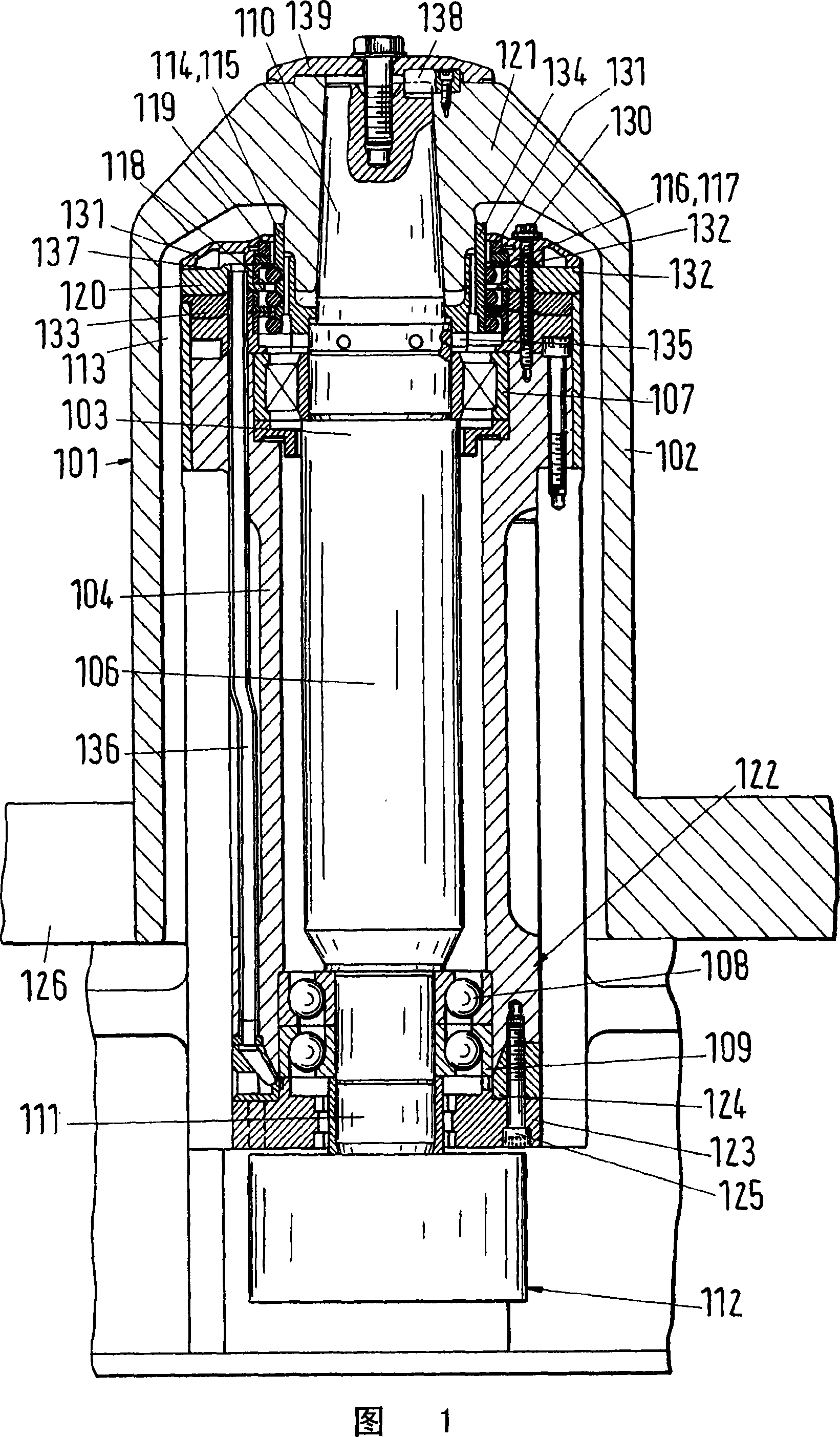
[0042] In the preferred prior art embodiment shown in FIG. 1 , the bearing arrangement comprises a drum 101 rotationally fixedly connected to a drive shaft 103 via a suspension 121 . A suspension 121 is located at the first end 110 of the drive shaft, said first end being conical in this embodiment. The conical shape is chosen in order to minimize the weakening of the drive shaft 103 by the notch effect. Each direct diameter transition of the drive shaft 103 is referred to as a weakening phenomenon under load leading to local load peaks, and these load peaks correspond to the notch effect. The drive shaft must bear not only the total load and torsional force of the drum 101, but also the power generated by the rotating motion of the drum and / or the drive shaft 103 itself. These dynamics introduce cyclically fluctuating alternating bending stresses into the shaft that can lead to fatigue failure, and it is known that fatigue failures of this type usually start from structural ...


PUM


Abstract

In a bearing assembly of a centrifugal revolving drum (1) around a spin axis (6), the revolving drum (1) is fixed by rotation through a drum hub (2) and a hanger bracket (21) of the revolving drum (1) and connected with a drive shaft (3). The drive shaft is connected with a drive set (12) and extends along the spin axis (6) in the bearing block (4, 7, 8, 9, 20, 24). The revolving drum (1) is supported on the bearing block (4, 7, 8, 9, 20, 24), thereby basically separating supporting force generated by power from the drive shaft (3).

Description

technical field [0001] The invention relates to a solution for the bearing of a drive shaft for a rotatable drum, and also to the sealing of such a bearing. The rotatable bowl is a component of a centrifuge, especially a vertical scraper centrifuge. Background technique [0002] This type of centrifuge is an example of a device used to separate a solid / liquid mixture into its solid and liquid components. During centrifugation, a separation process used to separate solid components from liquids, the solid / liquid mixture is rotated. Centrifugal forces acting on the solid and on the liquid lead to an increased sedimentation rate. The solid particles are moved away from the axis of rotation by centrifugal force in a plane perpendicular to the axis of rotation, in contrast to the sedimentation of the solid components of the mixture by the force of gravity acting on the particles. The particles are collected in a filter mounted rotationally symmetrically about the axis of rotat...

Claims


Application Information

Patent Timeline
Patent Type & Authority Applications(China)
IPC IPC(8): B04B9/08B04B15/00F16J15/16
CPCB04B9/12
Inventor L·斯特芬S·M·O·L·施奈德G·布什
Owner FERRUM
Why Eureka
Try Eureka