Supercharged ventilator

A ventilator and diffuser technology, which is applied in the direction of non-displacement pumps, non-variable pumps, machines/engines, etc., which can solve the problems of large lubricating oil consumption, large flow resistance of the centrifugal ventilator structure, and insufficient sealing pressure difference etc. to achieve the effect of reducing oil consumption

Inactive Publication Date: 2021-11-30
AECC SICHUAN GAS TURBINE RES INST
View PDF5 Cites 0 Cited by
  • Summary
  • Abstract
  • Description
  • Claims
  • Application Information

AI Technical Summary

Problems solved by technology

[0005] The purpose of the present invention is to provide a pressurized ventilator, which solves the technical problems of the existing centrifugal ventilator structure with large flow resistance and / or insufficient sealing pressure difference and / or large lubricating oil consumption at low engine speeds

Method used


Image

  • Supercharged ventilator
  • Supercharged ventilator
  • Supercharged ventilator

Examples


Embodiment 1

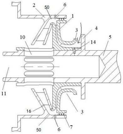
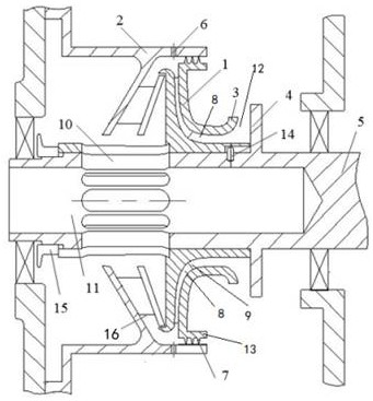
[0044] Such as figure 1 As shown, the pressurized ventilator is installed inside the gearbox, including a centrifugal compressor 1 and a diffuser 2. The centrifugal compressor 1 includes rotor blades 9, and an arc portion 3 is installed on the rotor blade 9. The arc portion 3 is "Trumpet" shape, arc radius 8mm. The gear oil pan 4 provided on the power transmission shaft 5, the distance between the oil gear pan 4 and one end of the adjacent arc portion 3 is 15mm, that is, the gap 12 is 15mm. The arc-shaped part 3 is installed on the rotor blade 9, and forms a narrow air flow channel (gradual structure setting, with figure 2 The placement direction is for reference, and the increase gradually changes from left to right), the purpose is to avoid a large number of lubricating oil particles from being inhaled. The air flow forms a vortex area on the arc portion 3 at the entrance of the centrifugal compressor 1, and after colliding with the oil retaining pan 4, a large number of ...

Embodiment 2

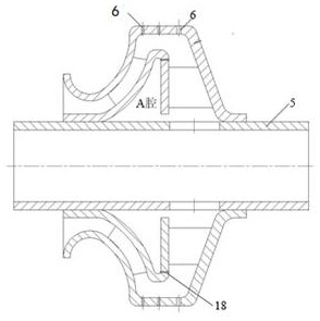
[0048] Such as image 3 As shown, the difference lies in that the centrifugal compressor 1 and the diffuser 2 are arranged in an integrated structure, installed on the transmission shaft 5, and can rotate together. A plurality of oil outlets 6 are provided in the transition area 50 to recycle the lubricating oil particles in the separated air for the second time, and there are a plurality of axial holes 18 on the housing, the diameter of which is Φ1mm, so as to avoid the A formed by the housing and the transmission shaft 5. Oil accumulation in cavity.

[0049] For the setting form of the rotor blades 9 on the above-mentioned center centrifugal compressor 1, see Figure 4 and 5 , can be composed entirely of long blades, or can be composed of long and short blades. In order to reduce the loss of the blades to lubricating oil particles, the number of blades should not be too many. When the blades are all long blades, the number can be up to 18. When the short blades are combin...


PUM

PropertyMeasurementUnit
thicknessaaaaaaaaaa

Abstract

The invention discloses a supercharged ventilator, belongs to the technical field of aero-engine lubricating systems, and solves the technical problems of high structure circulation resistance of an existing centrifugal ventilator and / or insufficient sealing pressure difference and / or high lubricating oil consumption of an engine in a low-rotating-speed state. The supercharged ventilator is suitable for exhausting of an aero-engine; the aero-engine comprises a gear box; the gear box comprises a shell, and a transmission shaft arranged in the shell; a diffuser and a centrifugal compressor are adjacently mounted in the shell; the centrifugal compressor is mounted on the transmission shaft, and is provided with an oil-gas separation structure; the diffuser is fixedly mounted on the inner surface of the shell; the diffuser and the centrifugal compressor are connected in a sealing and communicating mode; an oil phase and a gas phase of an oil-gas mixture exhausted by the gear box are separated through the oil-gas separation structure; separated oil is recovered by an oil pumping device; and separated gas is exhausted through the diffuser. The supercharged ventilator is used for improving the fuel recovery efficiency.

Description

technical field [0001] The invention belongs to the technical field of aero-engine lubricating systems, and in particular relates to a pressurized ventilator. Background technique [0002] The main shaft sealing system of an aero-engine is sealed by air with a certain pressure. During the working process of the engine, the sealed air will enter the bearing cavity of the lubrication system through the sealing device, and the air and lubricating oil are mixed in the bearing cavity to form an oil-air mixture. Allowing the oil and air to exit the bearing cavity directly will result in a large consumption of oil. . [0003] Ventilator performance indicators mainly include separation efficiency and flow resistance. Separation efficiency directly affects engine lubricating oil consumption, while flow resistance directly affects bearing chamber pressure. In order to meet the design index of low lubricating oil consumption, aero-engines are usually designed with high-speed ventilat...

Claims


Application Information

Patent Timeline
Patent Type & Authority Applications(China)
IPC IPC(8): F02C7/06F04D17/10F04D29/44F04D29/28F04D29/30F04D29/08B01D45/14
CPCF02C7/06F04D17/10F04D29/441F04D29/284F04D29/30F04D29/083B01D45/14
Inventor 陈以彪常柱宇付道鹏刘涛李贵林李炎军赵鹏程
Owner AECC SICHUAN GAS TURBINE RES INST
Why Eureka
Try Eureka