
Carding machine

A carding machine and pre-carding technology, which is applied in the field of carding machines, can solve the problems of inability to improve efficiency and inability to take out fiber webs, and achieve the effect of simplifying installation.

Pending Publication Date: 2018-10-23
TRUETZSCHLER GRP SE
View PDF13 Cites 1 Cited by
  • Summary
  • Abstract
  • Description
  • Claims
  • Application Information

AI Technical Summary

Problems solved by technology

Efficiency gains cannot be achieved here because the intermediate doffer cannot remove the web completely from the pre-carding cylinder

Method used


Image

  • Carding machine
  • Carding machine

Examples


Embodiment Construction

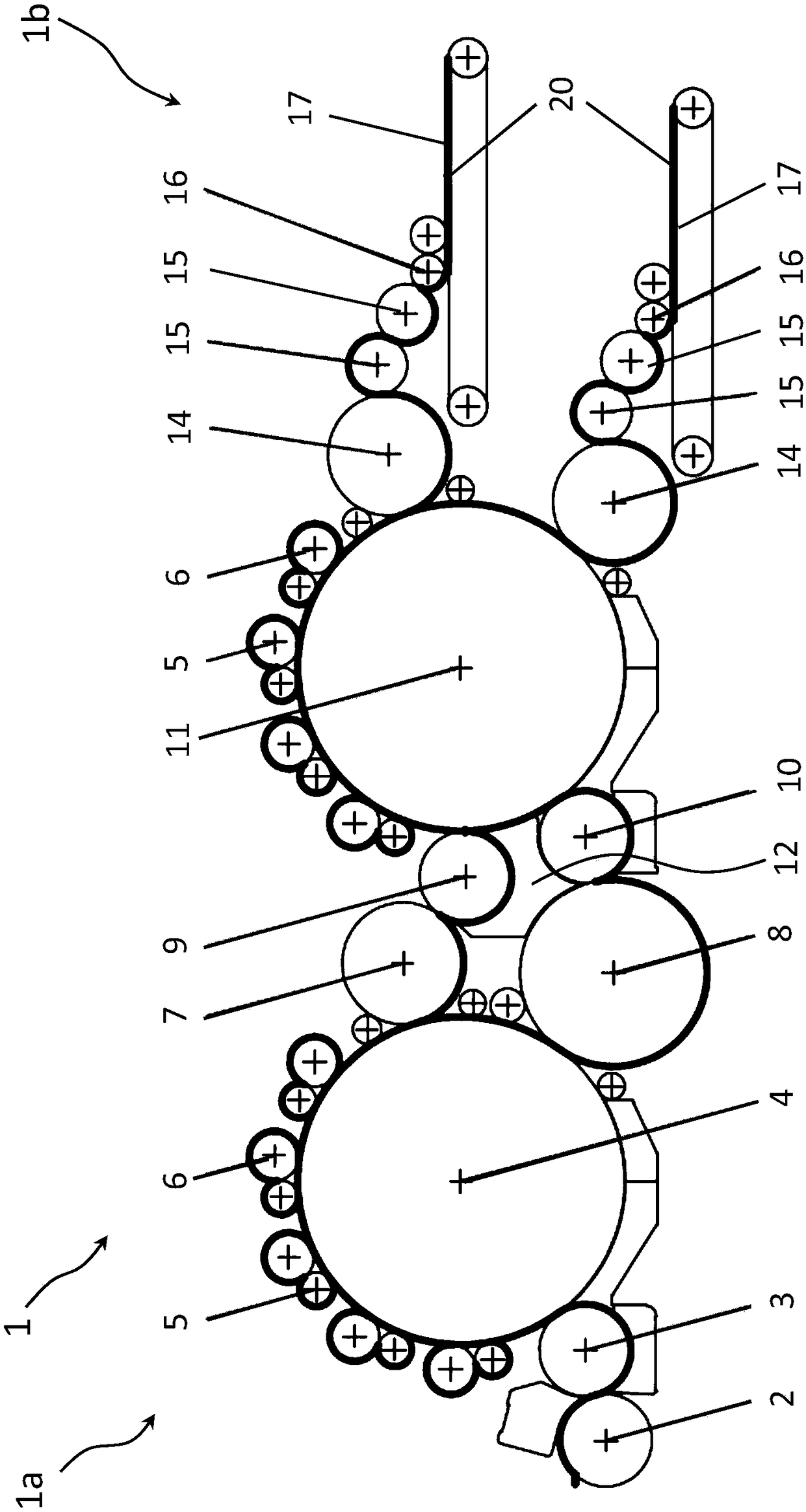
[0024] figure 1 A card 1 according to the invention is shown, which is designed as a card with a double transfer mechanism and has an inlet side 1 a for fiber fluff and one or more outlet sides 1 b for a fiber web 20 . In front of the feed side 1a of the carding machine 1 is installed a feeder not shown, such as a vibrating slide feeder, by means of which the fiber fluff is placed on a conveyor not shown. bring. Instead of a vibrating slide feeder, the card 1 can also be equipped with a card feeder with an integrated fiber material thickness gauge, in which card feeder the weight is determined by means of the fiber material thickness gauge, Alternatively, the fiber fluff is fed to the carding machine 1 by means of a direct feed.

[0025] In the card 1, the fiber fluff is conveyed to the device on the infeed side 1 a and is conveyed via rollers 2, 3 to a pre-combing drum 4, in which the fiber fluff is debonded in a first stage until it becomes individual fibers and are orie...


PUM

PropertyMeasurementUnit
diameteraaaaaaaaaa
diameteraaaaaaaaaa

Abstract

The invention relates to a carding machine provided with an inlet side (1a) for fiber plush, the fiber plush is conveyed to a pre-carding machine drum (4) and loosened until becoming a single fiber and being oriented, a first layer of fiber web is conveyed to a conveying roller (9) through an upper doffer (7) and then conveyed to a cylinder (11), a second layer of fiber web is conveyed to a conveying roller (10) through a lower doffer (8) and then conveyed to the cylinder (11), and at least one layer of fiber web is taken down from an outlet side (1b) of the carding machine through at least adoffer (14) to realize further processing. The carding machine is characterized in that the conveying rollers (9, 10) comprise the same diameters. Besides, the invention comprises a grid used in the carding machine.

Description

technical field [0001] The invention relates to a carding machine with an infeed side for fiber fluff, which is fed to a pre-carding cylinder and debonded until it becomes individual fibers and is oriented, wherein, by means of a doffer The first layer of web is transferred to the transfer roller and then onto the needle cylinder, wherein the second layer of web is transferred by means of a doffer to the transfer roller and then onto the needle cylinder, wherein for further processing by means of at least A doffer removes at least one layer of the web from the discharge side of the card. Furthermore, the invention relates to an associated drain base. Background technique [0002] The fiber fluff is debonded on a card until it becomes individual fibers. The resulting fiber web generally consists of fibers aligned in a specific direction, which can be specified, for example, by the machine direction (Machine Direction=MD). The fiber web has high stability in the machine dir...

Claims


Application Information

Patent Timeline
Patent Type & Authority Applications(China)
IPC IPC(8): D01G15/02D01G15/04D01G15/18D01G15/34D01G15/26
CPCD01G15/02D01G15/04D01G15/18D01G15/26D01G15/34D01G15/44D01G15/20
Inventor 博多·赫特克斯斯文·汤姆森君特·略弗金斯·沃福海科·思科弩特
Owner TRUETZSCHLER GRP SE
Learn More