Plate non-return valve with lateral downstream and control edge

A check valve and edge technology, which is used in the field of controlling the flow direction of the medium in the automobile, can solve the problems of opening the check valve, damaging the consumption of the connection, and the check valve cannot be opened according to the purpose, so as to reduce the impact speed and reduce the Noise generation and fatigue strength improvement effect

Inactive Publication Date: 2007-10-31
SCHAEFFLER KG
View PDF2 Cites 5 Cited by
  • Summary
  • Abstract
  • Description
  • Claims
  • Application Information

AI Technical Summary

Problems solved by technology

When the inlet and outlet sides of the check valve are subjected to fluctuating pressures, the check valve is often opened unintentionally due to fluctuations and superposition
When the check valve is suddenly opened or closed, a pressure spike occurs in the system due to the inertia of the transmission fluid c

Method used


Image

  • Plate non-return valve with lateral downstream and control edge
  • Plate non-return valve with lateral downstream and control edge
  • Plate non-return valve with lateral downstream and control edge

Examples


Embodiment Construction

[0034] The same or similar components are provided with the same symbols in different figures. The presentations are schematic and not comprehensive.

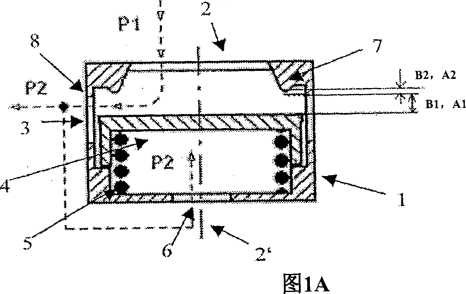
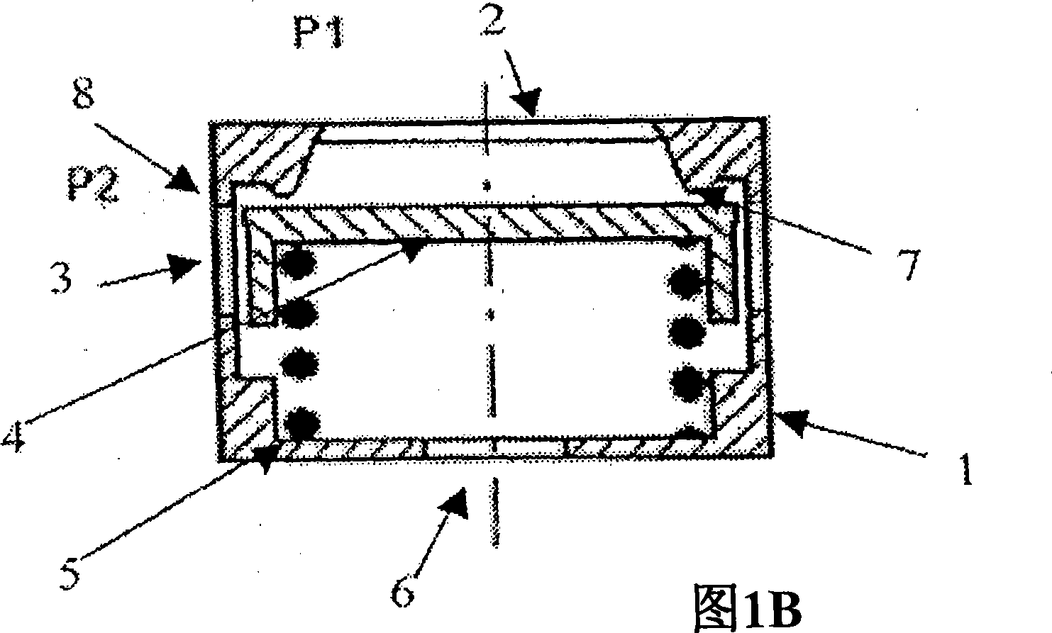
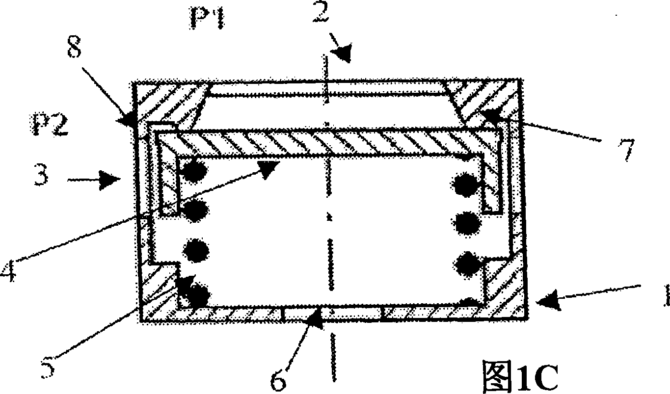
[0035] 1A to 1C show a check valve device for an automobile according to an exemplary embodiment of the present invention. The non-return valve has a valve sleeve 1 with an inflow opening 2 and an outflow opening 3 , and a valve element 4 which is displaceably mounted in the valve sleeve 1 . When the valve element 4 is in the first position, a first flow cross section A1 between the outflow opening 3 and the valve element 4 is adjusted ( FIG. 1A ). The outflow connection 3 is closed by the valve element 4 when the valve element 4 is in the second position. Therefore no flow cross section is provided. When the valve element 4 moves in the first movement area B1 and the second movement area B2, the liquid flow cross-section A will change continuously. Wherein, the continuous change of the liquid flow cross-section A in the fi...


PUM


Abstract

The invention relates to a check valve for vehicle. The check valve apparatus has a valve housing and valve unit. The device has a valve housing with inlet and outlet openings, and sealed edge. The valve unit is movably supported in the housing. A flow cross section (A1) is formed between the outlet opening and the unit, when the unit is arranged in the first position. The outlet opening is closed by the unit when the unit is arranged in a second position. Meanwhile, the valve unit is movably supported between two positions. When the valve element moves in the first mobile area, the flow cross section (A1) continuously changes and provides a reduced flow cross section (A2) relative to the first flow cross section when the valve unit moves in the second mobile area. When the valve unit is in the second position, the valve unit is at the sealed edge.

Description

technical field [0001] The invention relates to a non-return valve arrangement for a motor vehicle and a method for controlling the flow direction of a medium in a motor vehicle. The invention also relates to the use of the non-return valve arrangement in camshaft adjustment systems, in hydraulic belt or chain tensioning systems and in motor vehicles. Background technique [0002] A check valve is provided in the hydraulic pressure system of the vehicle, which is used to control a certain flow direction of the hydraulic medium, which can be opened in a certain flow direction and closed in the opposite flow direction. Hydraulic pressure systems, such as camshaft adjustment systems and chain tensioning or belt systems, often constitute a considerable amount of consumption in motor vehicles. As a result, transmission fluid loss often occurs at various points in the hydraulic system, resulting in pressure peaks and fluctuating pressures. This places particularly high demands o...

Claims


Application Information

Patent Timeline
IPC IPC(8): F01L1/34F01L1/348
CPCF01L1/3442F16H2007/0859F16K15/028
Inventor 马可·施米特
Owner SCHAEFFLER KG
Why Eureka
Try Eureka