Ball screw rod composite set

A combined device and ball screw technology, which is applied in transmission devices, belts/chains/gears, mechanical equipment, etc., can solve problems affecting the circulation smoothness of return components, extrusion damage, ball drop, etc.

Active Publication Date: 2007-10-31
HIWIN TECH
View PDF0 Cites 3 Cited by
  • Summary
  • Abstract
  • Description
  • Claims
  • Application Information

AI Technical Summary

Problems solved by technology

[0002] At present, the rolling element return circulation of the ball screw is divided into the internal circulation mode or the end cover type circulation mode. Please refer to Figure 1, which is a commonly used combined perspective view, that is, the structure with the axial through hole of the nut as the return mode. In the figure The end plug 10 is fixed in the end plug fixing groove 201 on the end surface of the nut 20. The end plug 10 is provided with a turning path 101 of the ball 11, and the end plug 10 is pushed into the end plug fixing groove 201 along the axial direction of the nut 20. , until the axial positioning part 102 on the end plug 10 is positioned in the end plug fixing groove 201 of the nut 20 to limit the axial freedom of the end plug 10, and then the fixing screw 30 is passed through the fixing hole 202 of the nut 20 Insert and lock through the locking hole 103 of the end plug 10 to limit the radial freedom of the end plug 10. According to this assembly and matching method, a tooth groove 402 needs to be provided on the outer diameter of the screw shaft 40, the so-called teething The groove 402 refers to the groove provided on the outer diameter of the screw shaft 40 for the rolling of the ball 11 and connected to the bearing surface 403 of the shoulder 401 to avoid interference between the end plug 10 and the screw shaft 40 , so when the screw shaft 40 When there is no tooth groove 402 on the outer diameter of the
[0003] The ball screw assembly method must first have teeth grooves 402 on the shoulder 401 of the screw shaft 40, so the teeth grooves 402 distributed on the outer diameter of the screw shaft 40 need to be produced by machining, which will make the screw shaft 40 The bearing surface 403 of the shoulder 401 leaves a tooth notch 404, and the structure of this tooth notch 404 will be affected by the following factors and cause the screw shaft 40 to be impractical:
[0004] One, the tooth groove 402 of the current screw shaft 40 will leave a tooth groove gap 404 on the bearing surface 403 of the screw shaft shoulder 401, causing the diameter of the bearing surface 403 to be incomplete. The two ends of 40 are installed on the bearing seat (not shown) of the machine table, and the motor of the machine table is activated to make the screw shaft 40 in a running state. The two ends of the screw shaft 40 will generate axial force load due to the rotational inertia, And this axial force load will present non-integrity factors because of the diameter of the bearing surface, resulting in the uneven distribution of the axial force load at both ends of the screw shaft 40, except that the end surface of the bearing installed on the bearing seat of the machine (not shown In addition to causing extrusion damage, the phenomenon of deflection and deformation of the screw shaft 40 during operation will directly affect the smoothness of the circulation of the return assembly, and will also reduce the service life of the ball screw, which is not in line with the economic benefits of use.
[0005] Second, when the two ends of the screw shaft 40 are installed on the bearing seat on the machine table, the nuts 20 are inserted into the screw shaft 40 and filled with balls in sequence, and are assembled manually as a ball screw, during which it is possible to The step of matching and adjustment is required. Due to the factors generated in this step, the nut 20 and the screw shaft 40 will separate or the nut 20 will over-travel, causing the ball to unscrew and drop.

Method used


Image

  • Ball screw rod composite set
  • Ball screw rod composite set
  • Ball screw rod composite set

Examples


Embodiment Construction

[0038] In order to achieve the above-mentioned purpose, the technology adopted, the means and other effects of the invention of this case, and after the description of the embodiment in conjunction with Fig. Get a deep and specific understanding.

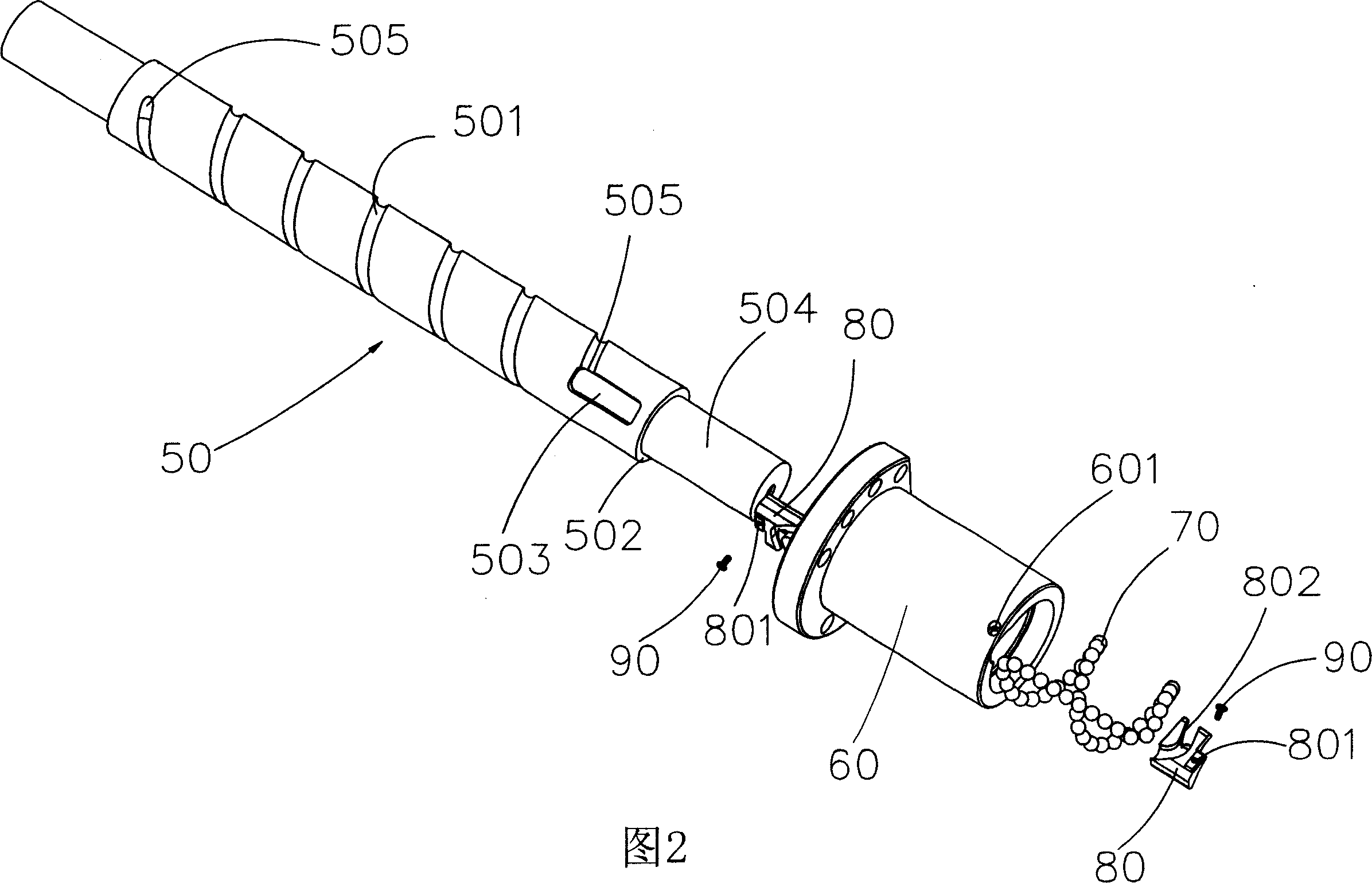
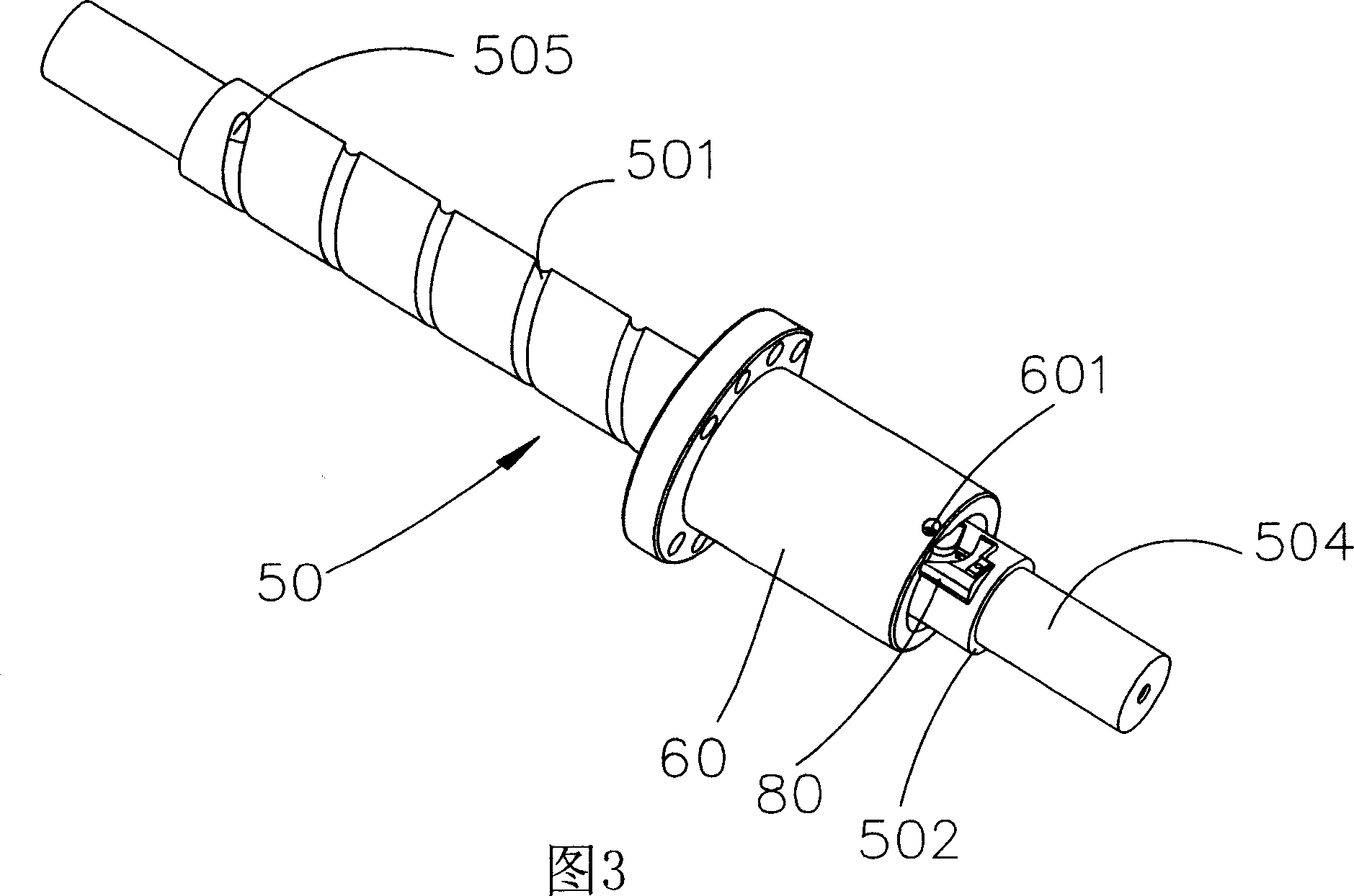
[0039] In order to clearly illustrate the preferred embodiment of the present invention, the various components and action changes of the preferred embodiment are described below, and Fig. 2 and Fig. 3 are the decomposition and assembly perspective views of the present invention, and its structural description is described as follows:

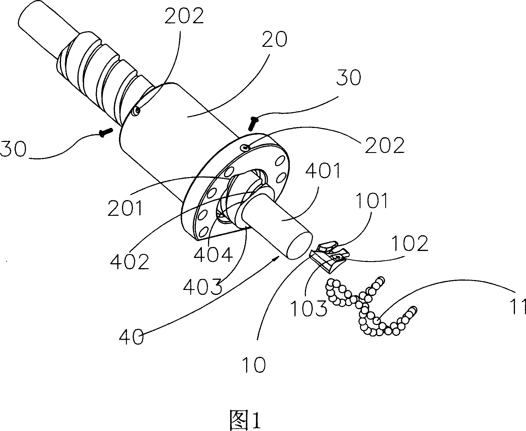
[0040] First, the present invention is a ball screw combination device, which mainly includes: a screw shaft 50, a nut 60, a ball 70 and an end plug 80, wherein the nut 60 is passed through the screw shaft 50, and the end plug After 80 is inserted into the nut 60, the set screw 90 is inserted through the fixing hole 601 of the nut and locked through the locking hole 801 of the end plug 80, so that th...


PUM


Abstract

The invention is a combination device of ball and screw, which is characterized in that the shoulder of the screw shaft is provided with barren teeth slot and the end of screw shaft is provided with a escaping-cut portion, wherein the escaping-cut portion is connected with a barren teeth end of the barren teeth slot to the finger of the end plug can move axially with the cap to screw into the barren teeth slot, and the invention can realize the assembly of the cap, avoids the ball screwing out and dropping off during the separation of the cap and the screw shaft or the cap is over-stroke and prevents the deflection and deformation in the operation to assure the using life of the ball and screw.

Description

technical field [0001] The invention relates to a ball screw combination device, in particular to a screw shaft, which is mainly provided with an unextruded tooth groove on the shoulder of the screw shaft, and an escape cut part is provided at the end of the screw shaft, and the escape cut part and The tooth sockets communicate with each other, so that the nail portion of the end plug can be screwed into the tooth sockets correspondingly with the axial movement of the nut, so that the assembly and cooperation of the nut can be completed. Background technique [0002] At present, the rolling element return circulation of the ball screw is divided into the internal circulation mode or the end cover type circulation mode. Please refer to Figure 1, which is a commonly used combined perspective view, that is, the structure with the axial through hole of the nut as the return mode. In the figure The end plug 10 is fixed in the end plug fixing groove 201 on the end surface of the n...

Claims


Application Information

Patent Timeline
Patent Type & Authority Applications(China)
IPC IPC(8): F16H25/22
Inventor 陈彦羽陈新和
Owner HIWIN TECH
Why Eureka
Try Eureka