
Phase-shift mask providing balanced light intensity through different phase-shift apertures and method for forming such phase-shift mask

A technology of light intensity and photomask, applied in the field of photomask, can solve the problems of easy falling off of the pattern forming layer, irreparable repair of the photomask, breakage, etc.

Inactive Publication Date: 2007-10-31
TOPPAN PHOTOMASKS INC
View PDF0 Cites 6 Cited by
  • Summary
  • Abstract
  • Description
  • Claims
  • Application Information

AI Technical Summary

Problems solved by technology

However, etched portions of the substrate beneath the patterning layer can result in overhangs of the patterning layer that can break off during various processes such as aggressive cleaning processes, causing irreparable defects in the photomask
Also, in applications utilizing thin patterning layers such as the sub-300nm patterning layer used in sub-75nm node designs, the patterning layer may be easily delaminated, resulting in defective photomasks

Method used


Image

  • Phase-shift mask providing balanced light intensity through different phase-shift apertures and method for forming such phase-shift mask
  • Phase-shift mask providing balanced light intensity through different phase-shift apertures and method for forming such phase-shift mask
  • Phase-shift mask providing balanced light intensity through different phase-shift apertures and method for forming such phase-shift mask

Examples


Embodiment Construction

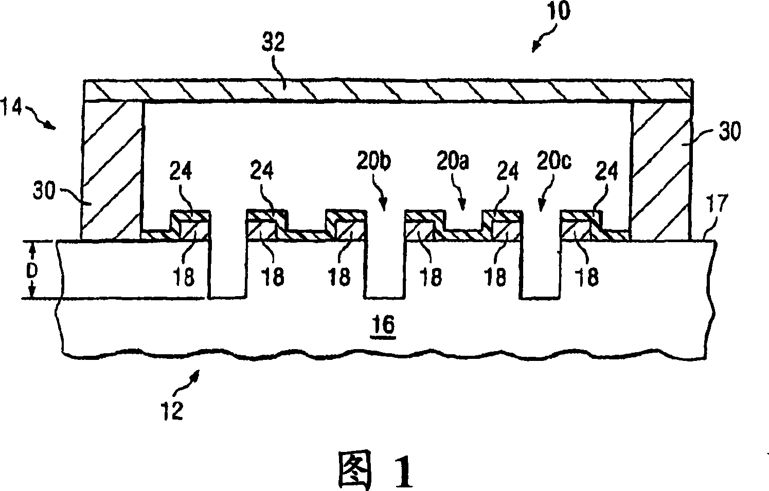
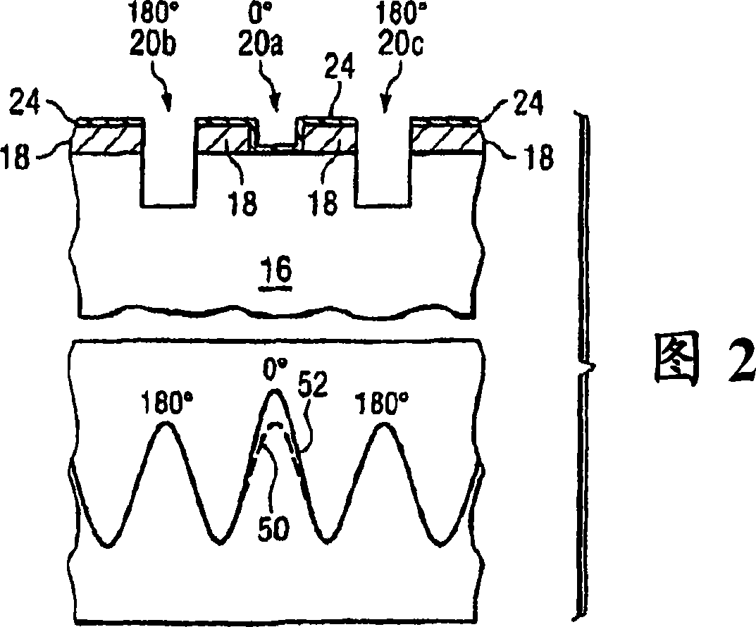
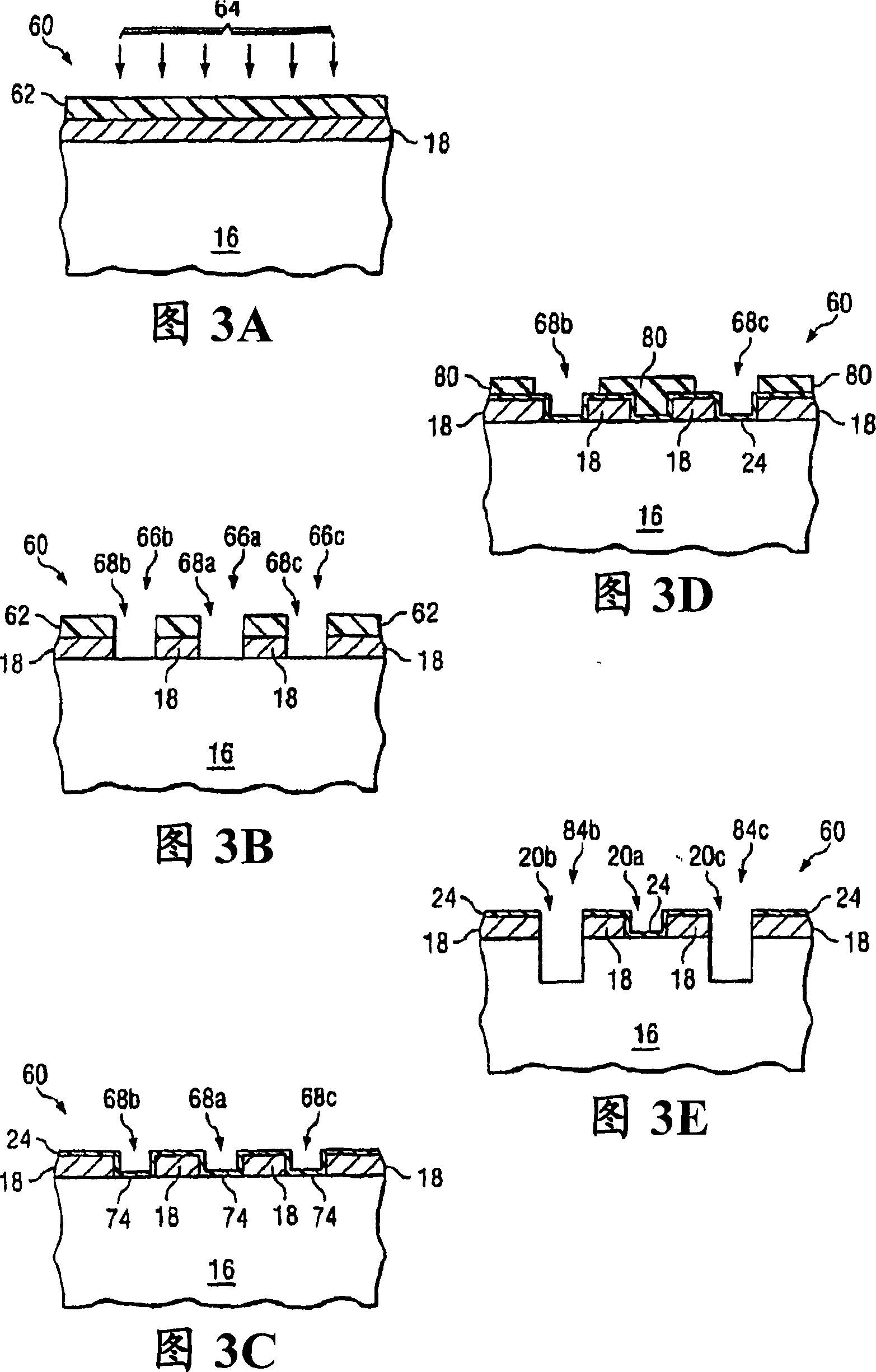
[0020] The preferred embodiment of the present invention and its advantages are best understood by referring to Figures 1 through 3E, wherein like numerals are used to indicate like and corresponding parts.

[0021] Figure 1 illustrates a cross-sectional view of an example photomask assembly 10 in accordance with some embodiments of the present invention. Photomask assembly 10 may include a pellicle assembly 14 mounted on photomask 12 . Substrate 16 and patterning layer 18 may form photomask 12, or mask or reticle, which may have a wide variety of sizes and shapes including, but not limited to, circular, rectangular or square. Photomask 12 may also be any of a variety of photomask types including, but not limited to, a primary reticle, a 5-inch reticle, a 6-inch reticle, a 9-inch reticle, or any other suitable size reticle. Boards that can be used to project images of circuit patterns onto semiconductor wafers. Photomask 12 may be a phase shift mask (PSM), such as, for exam...


PUM

PropertyMeasurementUnit
thicknessaaaaaaaaaa
transmittivityaaaaaaaaaa

Abstract

A photomask may include a patterned layer, a phase-shift layer adjacent the patterned layer, a first aperture, a second aperture, and a light-absorbing layer. The first aperture may allow light to pass through the patterned layer and the phase-shift layer and provide a first phase shift. The second aperture may allow light to pass through the patterned layer and the phase-shift layer and provide a second phase shift different than the first phase-shift. The light-absorbing layer may be disposed adjacent the first aperture and may include a light-absorbing material that reduces the intensity of light passing through the first aperture such that the intensity of light passing through the first aperture is substantially equal to the intensity of light passing through the second aperture.

Description

[0001] Cross References to Related Applications [0002] This application claims U.S. Provisional Patent Application entitled "Phase Shift Mask Providing Balanced Light Intensity Through Different Phase Shift Apertures and Method of Forming Such Phase Shift Mask" by Gong Chen et al., filed September 26, 2005 Priority of No. 60 / 613,343, the entire contents of which are hereby incorporated by reference. technical field [0003] The present invention relates generally to photomasks, and more particularly to phase shift masks that provide balanced light intensity through different phase shift apertures and methods of forming such phase shift masks. Background technique [0004] In a typical alternating aperture phase shift mask (AAPSM), the intensity of light transmitted through a 180 degree aperture is generally less than that transmitted through a 0 degree aperture because the 180 degree aperture is associated with an etched quartz structure. As a result, the...

Claims


Application Information

Patent Timeline
Patent Type & Authority Applications(China)
IPC IPC(8): G01F9/00G03F9/00G03C5/00G03F1/00
CPCG03F1/30
Inventor G·陈F·D·卡尔克
Owner TOPPAN PHOTOMASKS INC
Learn More