Sensor arrangement

A sensor device and detector technology, which is applied to measurement devices, instruments, and the use of electromagnetic/magnetic devices to transmit sensing components to achieve the effect of low energy consumption

Inactive Publication Date: 2007-10-31
NXP BV
View PDF1 Cites 19 Cited by
  • Summary
  • Abstract
  • Description
  • Claims
  • Application Information

AI Technical Summary

Problems solved by technology

The sensor devices in Figures 6 and 7 are very sensitive to in-p

Method used


Image

  • Sensor arrangement
  • Sensor arrangement
  • Sensor arrangement

Examples


Embodiment Construction

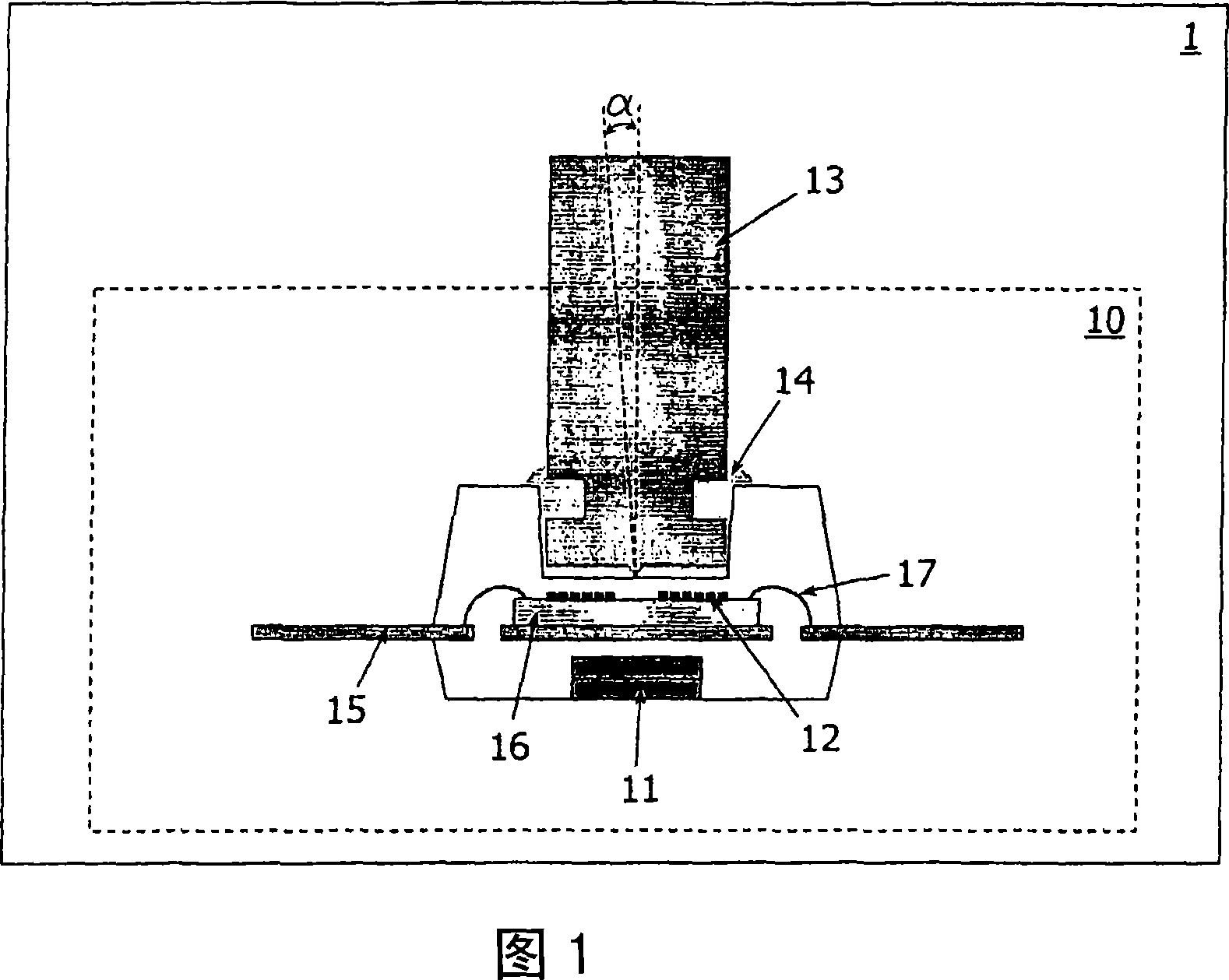
[0044] In portable PCs or small handheld electronic devices, such as mobile phones, PDAs, digital cameras or GPS devices, devices with analog pointing functions are often required. Various designs of analogue pointing devices, for example piezoelectric or optical pointing devices, already exist on the market. Piezoelectric pointing devices require sophisticated microcontrollers to compensate for sensor drift. Optical pointing devices are feasible, but consume relatively high power. In the present invention, the proposed magnetic pointing device has a simple structure, relatively simple required electronic components, low power consumption, and can be fully integrated in a semiconductor chip package.

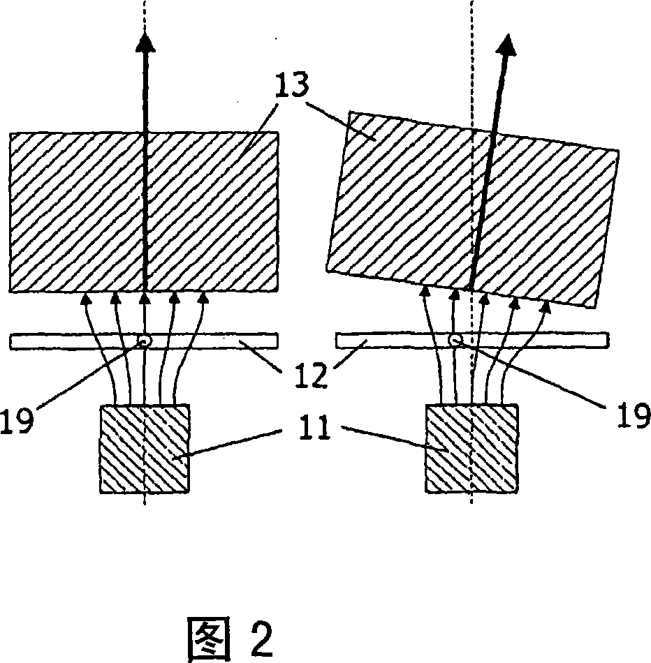
[0045]The apparatus 1 according to the invention shown in FIG. 1 comprises a sensor arrangement 10 according to the invention. The sensor device 10 comprises a field generator 11 for generating a field, for example a magnet for generating a magnetic field. The sensor device 10...


PUM


Abstract

Devices (1) comprising sensor arrangements (10) with field detectors (12) for detecting components (18) of magnetic fields in planes of the field detectors (12) and with movable objects (13) for, in response to tilting movements, changing at least parts of the components (18) of the magnetic fields in the plane; of the field detectors (12) are made less sensitive to in-plane stray fields by providing the fold detectors (12) with saturated field-dependent elements (31). The movable object (13) 1 nay comprise a movable field generator for generating the magnetic field, or the movable of object (13) and the field generator (11) may be different objects. The magnetic field is such that the field-dependent element (31) is saturated. The field generator (11) is smaller than the field detector (12), and the movable object (13) is larger than the field detector (12), to reduce alignment problems. The movable object (13) has a pivoting point close to the field detector (12).

Description

technical field [0001] The invention relates to a device comprising a sensor device, and also to a sensor device and a sensing method. [0002] Examples of such devices are portable PCs and small handheld electronic devices such as mobile phones, personal digital assistants, digital cameras, and global positioning system devices. Background technique [0003] This device is known from German patent application DE 43 17 512 A1. Figure 6 of this document discloses a sensor arrangement with a movable magnet and a field detector. Figure 7 discloses a sensor device with a fixed magnet directly below the field detector and an indicator comprising a ferromagnetic material above the field detector. Field detectors are only sensitive to in-plane field components. The sensor arrangement in Figures 6 and 7 is very sensitive to in-plane stray magnetic fields, which is considered a disadvantage. Contents of the invention [0004] It is an object of the invention to provide a device...

Claims


Application Information

Patent Timeline
IPC IPC(8): G06F3/033G01R33/09G01R17/10G01D5/16G06F3/0338
CPCG01R33/096H01L2224/48091H01L2224/48247H01L2924/181H01L2924/1815
Inventor 汉斯·范索恩亚普·鲁伊格罗克让·C·范德霍芬金·攀尔
Owner NXP BV
Why Eureka
Try Eureka