Force balancing resonance micro-mechanical gyro

A technology of micro-mechanical gyroscope and force balance, which is applied in the direction of speed measurement by gyro effect, gyroscope/steering sensing equipment, measuring device, etc., and can solve the problems of insufficient sensitivity and resolution of micro-mechanical gyroscope

Inactive Publication Date: 2007-11-07
BEIHANG UNIV
View PDF0 Cites 25 Cited by
  • Summary
  • Abstract
  • Description
  • Claims
  • Application Information

AI Technical Summary

Problems solved by technology

[0004] The technical problem of the present invention is: to overcome the deficiencies of the prior art, to provide a force-balanced resonant micro-machined gyroscope, t

Method used


Image

  • Force balancing resonance micro-mechanical gyro
  • Force balancing resonance micro-mechanical gyro
  • Force balancing resonance micro-mechanical gyro

Examples


Embodiment Construction

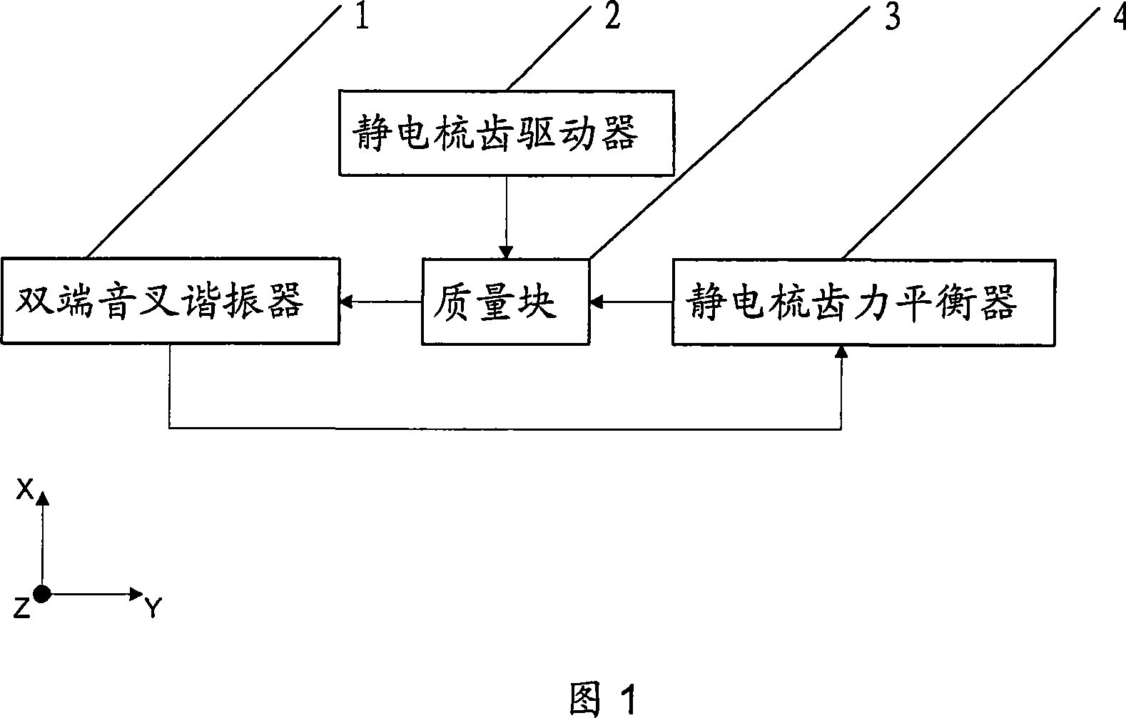
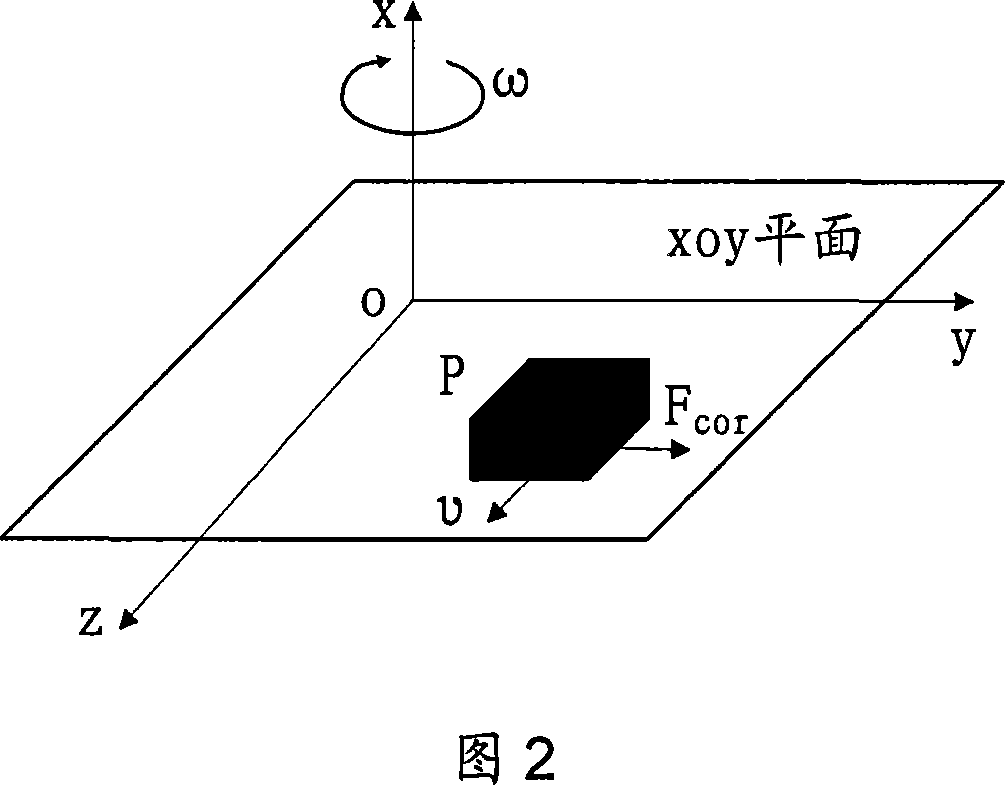
[0020] As shown in Fig. 1, the present invention consists of four parts: a double-ended tuning fork resonator 1, an electrostatic comb driver 2, a mass block 3, and an electrostatic comb force balancer 4, and the entire structure is an axisymmetric figure. The mass block 3 is in the middle position and has two degrees of freedom in x and y directions. Two electrostatic comb drives 2 fixed on the base are symmetrically placed in the x direction, and two electrostatic comb drives 2 fixed on the base are symmetrically placed in the y direction. Electrostatic comb force balancer 4 and two double-ended tuning fork resonators DETF 1.

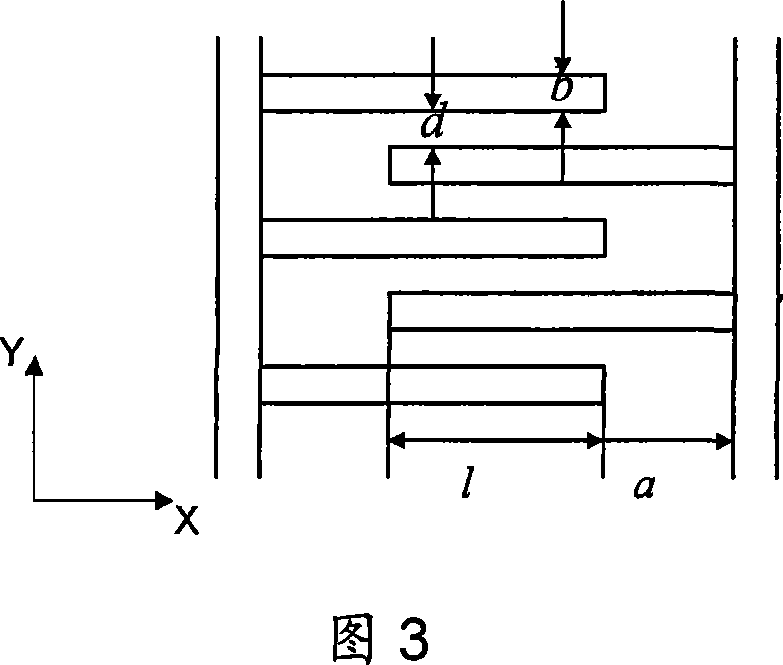
[0021] As shown in Figure 4, the double-ended tuning fork resonator 1 includes a driving static tooth 6, a measuring static tooth 7, a beam 11 and a movable tooth 5, wherein two symmetrical tuning fork beams perform simple harmonic vibration, and the driving static teeth 6 and The movable tooth 5 constitutes a pair of dynamic and static comb teeth, an...


PUM


Abstract

The invention relates to an equilibrium type resonance micro mechanical top, which includes static comb tooth driver, mass block, double end tuning fork resonator and static comb tooth strength balancer. When adds the driving voltage to the static comb tooth driver, the mass block does along x axis direction oscillation motion, and circles the z axis in exterior under the rate of angular motion function to produce along y direction coriolis force. The static comb tooth strength balancer used to balance the mass block in y direction Coriolis force and keep the mass block in the equilibrium position of the y direction. The invention structural style enhanced the micro mechanical top sensitivity, the resolution and the dynamic range and realized Coriolis force change, which had the top sensitive angular speed to transform the resonator resonance frequency change, and then through the feedback return route adjustment achieved the new balanced equilibrium type feedback system, and effectively suppressed the non-linear influence.

Description

technical field [0001] The invention belongs to the field of micro-mechanical sensors in micro-electro-mechanical systems (MEMS), and is widely used in the fields of automotive electronics, aerospace, weaponry and the like as a micro-inertial device. Background technique [0002] The classic frame-type mechanical rotor gyroscope based on the principle of angular momentum is assembled from hundreds of (about 300) parts. It has a complex structure, large volume, and short service life, which cannot meet the requirements of technological development and many new applications. Therefore, solid-state gyroscopes without mechanical rotors have been developed one after another, such as laser gyroscopes, hemispherical resonant gyroscopes, and fiber optic gyroscopes. The performance of the first two gyroscopes can reach the drift accuracy of inertial navigation (0.01° / h); but the price is high and the volume is large, which is still not suitable for the needs of the developing miniatu...

Claims


Application Information

Patent Timeline
IPC IPC(8): G01C19/56G01C19/5621
Inventor 樊尚春王莹莹蔡晨光
Owner BEIHANG UNIV
Why Eureka
Try Eureka