Image display and its driving method
一种图像显示装置、驱动方法的技术,应用在静态指示器、仪器等方向,能够解决Vth校正范围有限、Vth校正困难等问题,达到提高像质可靠性、容易阈值电压补偿、改善均一化的效果
- Summary
- Abstract
- Description
- Claims
- Application Information
AI Technical Summary
Problems solved by technology
Method used
Image
Examples
Embodiment 1
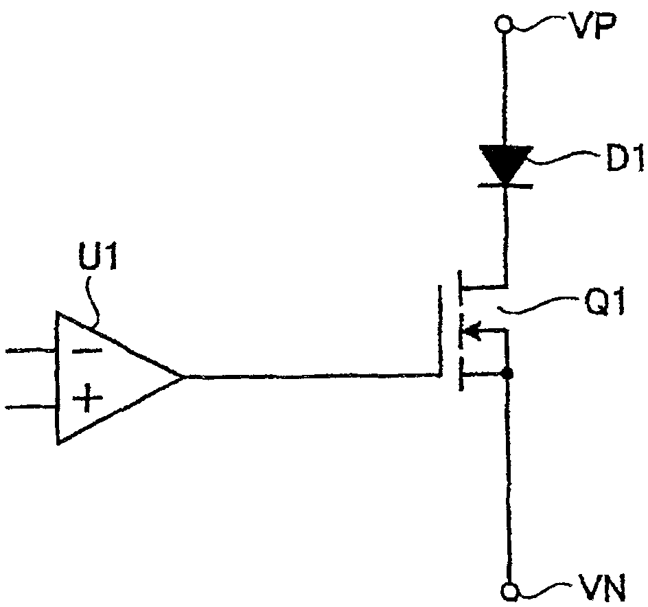
[0097] Figure 7 to represent figure 1 In the pixel circuit shown in , the relationship between the lighting time of the driving element Q1 and the threshold voltage shift ΔV under the condition that no reverse bias is applied to the driving element Q1 is shown. Figure 8 as well as Figure 9 to express to figure 1 The graph of the relationship between the lighting time of the driving element Q1 and the threshold voltage drift under the condition that the driving element Q1 in the pixel circuit shown in FIG. 1 is loaded with a reverse bias. in addition, Figure 8 as well as Figure 9 In the process, work repeatedly with the lighting time of 10 minutes and the non-lighting time of 20 minutes, especially Figure 8 The case where the reverse bias voltage is "-1V" is shown in , Figure 9 The case where the reverse bias voltage is "-5V" is shown in .
[0098] like Figure 7 As shown, in the case of no reverse bias, about 60 hours of continuous operation, a threshold volta...
Embodiment 2
[0105] Figure 10 and Figure 11 are respectively denoted with Figure 7 or Figure 9 A graph of the characteristics of the same situation. and Figure 10 The characteristics shown in , show the following situation: that is, repeated with the lighting time of 3 minutes and the non-lighting time of 17 minutes, continuous use of 16 hours in the daytime, 8 hours of non-lighting at night, and the non-lighting time at night , Simply open the gate, source, and drain voltages of the drive element. in addition, Figure 11 The following situation is shown in the figure: that is, repeat the lighting time of 3 minutes and the non-lighting time of 17 minutes, continue to use it for 16 hours during the day, and keep it off for 8 hours at night, and when it is not lit at night, the drain-source The inter-electrode voltage was maintained at the same potential, and a reverse bias of -5V was applied to the gate-source voltage during the first hour of non-lighting, and 0V was maintained d...
Embodiment 3
[0109] Figure 12 In order to show the characteristics in the case where the operation is repeated with a lighting time of 3 minutes and a non-lighting time of 17 minutes, and a reverse bias of -5V is applied between the gate and the source only in the first 5 minutes of non-lighting diagram. As shown in the figure, the time-dependent deterioration of the threshold voltage can be prevented even in the case where the reverse bias is applied only for the first 5 minutes of the 17 minutes of non-lighting.
[0110] Additionally, if the Figure 12 The features shown in the Figure 9 Compared with the characteristics shown in , even with the same reverse bias voltage of -5V, the loading time of the reverse bias is longer Figure 9 ( Figure 9 :20 minutes, Figure 12 : 5 minutes) On this side, the dispersion of the threshold voltage shift is smaller. In addition, if the Figure 11 The features shown in the Figure 9 Compared with the characteristics shown in the reverse biase...
PUM
 Abstract
Description
Claims
Application Information
 - R&D
- Intellectual Property
- Life Sciences
- Materials
- Tech Scout
- Unparalleled Data Quality
- Higher Quality Content
- 60% Fewer Hallucinations
Browse by: Latest US Patents, China's latest patents, Technical Efficacy Thesaurus, Application Domain, Technology Topic, Popular Technical Reports.
© 2025 PatSnap. All rights reserved.Legal|Privacy policy|Modern Slavery Act Transparency Statement|Sitemap|About US| Contact US: help@patsnap.com


