

Method and device for sensitivity compensation
A technology of given position, input position, applied in recording/reproduction by optical method, configuration/installation of head, packaging, etc., can solve problems such as spindle motor misalignment
- Summary
- Abstract
- Description
- Claims
- Application Information
AI Technical Summary
Problems solved by technology
Method used
Image

Examples
Embodiment Construction
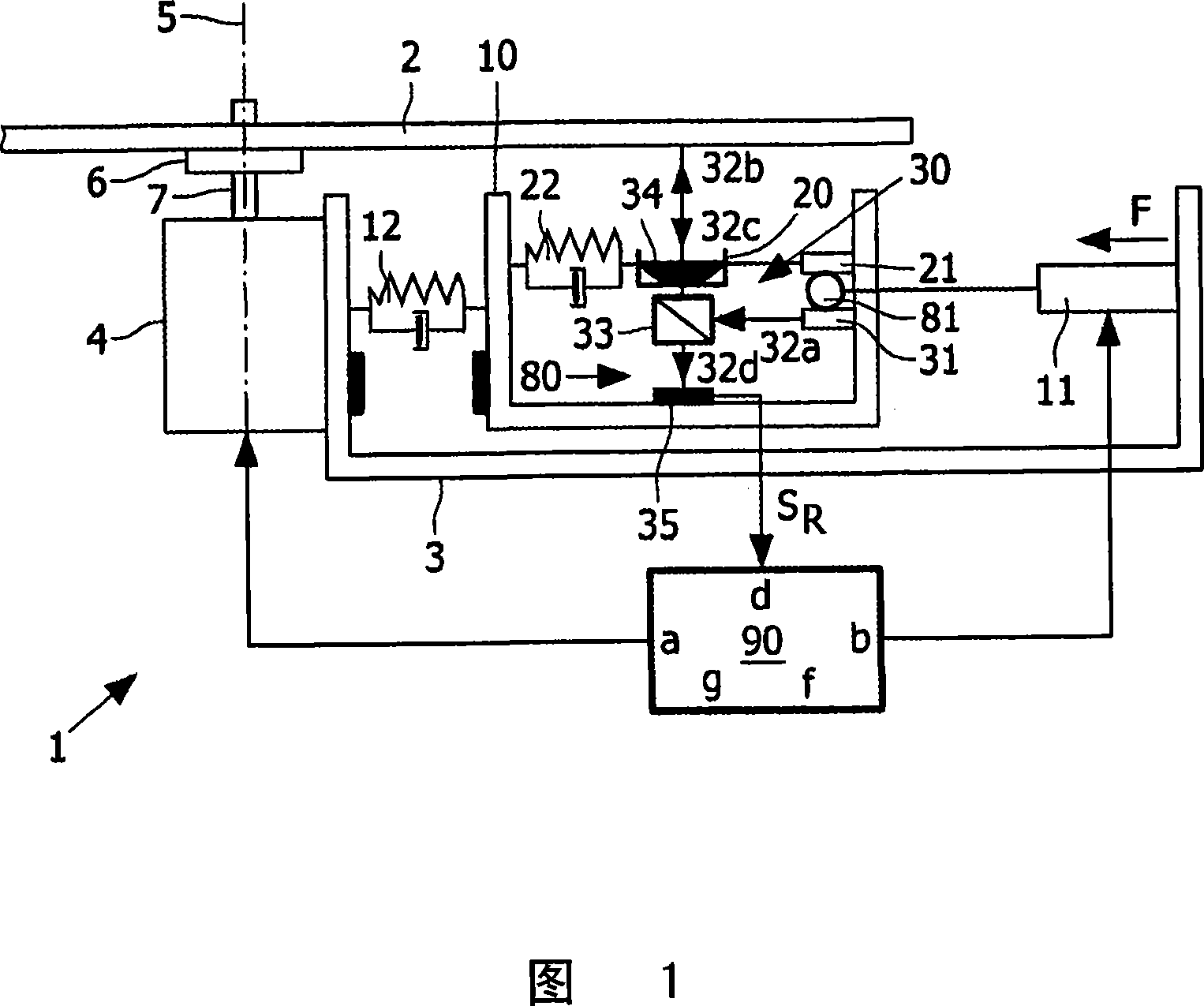
[0056] Figure 1 schematically shows an optical disc drive 1 receiving an optical disc 2 for reading or writing. The drive 1 comprises a housing 3 containing a motor 4 with a rotational axis 5 . The disc 2 is held by a flange 6 mounted on a spindle 7 .
[0057]Furthermore, the housing comprises a pick-up unit in the form of a carriage 10 which is movable substantially linearly in the radial direction of the disc 2 . The carriage 10 is moved by applying a force F on the carriage by radial carriage actuators 11 . The actuator forms a radial coupling as shown at 12 between the carriage 10 and the housing 3 with elastic, rigid and damping properties. The actuator 11 may be a linear motor, a stepper motor or a worm gear motor.
[0058] Furthermore, the pick-up unit includes a platform 20 arranged on a carriage and movable in radial and axial directions. The platform actuator 21 forms a radial and axial coupling as shown at 22 between the platform and the carriage with elastic, r...
PUM
 Abstract
Description
Claims
Application Information