Square-pipe punching machine

A punching machine and punching technology, applied in the direction of punching tools, metal processing, metal processing equipment, etc., can solve the problems of many burrs, low processing efficiency, affecting assembly and use, etc., to achieve smooth punching surface and high processing efficiency , beautiful appearance effect

Inactive Publication Date: 2007-11-14
庄添财
View PDF0 Cites 16 Cited by
  • Summary
  • Abstract
  • Description
  • Claims
  • Application Information

AI Technical Summary

Problems solved by technology

[0003] When using traditional technology to punch pipe fittings, it is very easy to cause the outer wall of the pipe fittings to sag inwards, and there will be more burrs on the inner wall, especially when processing large shelve

Method used


Image

  • Square-pipe punching machine
  • Square-pipe punching machine
  • Square-pipe punching machine

Examples


Example Embodiment

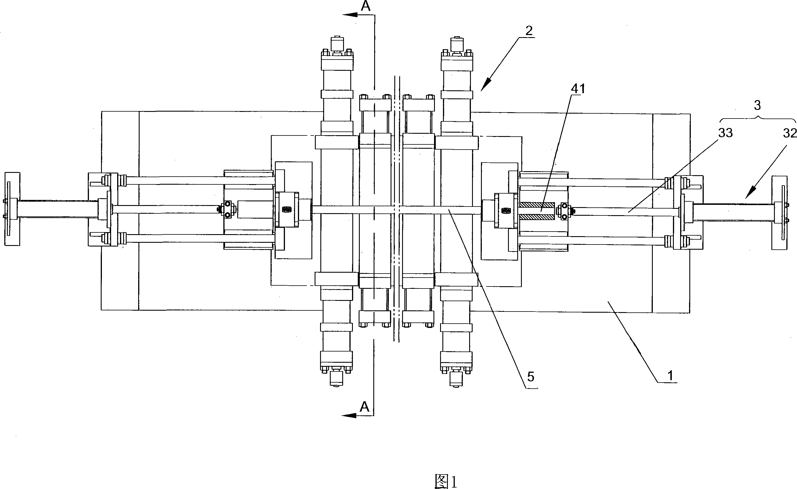
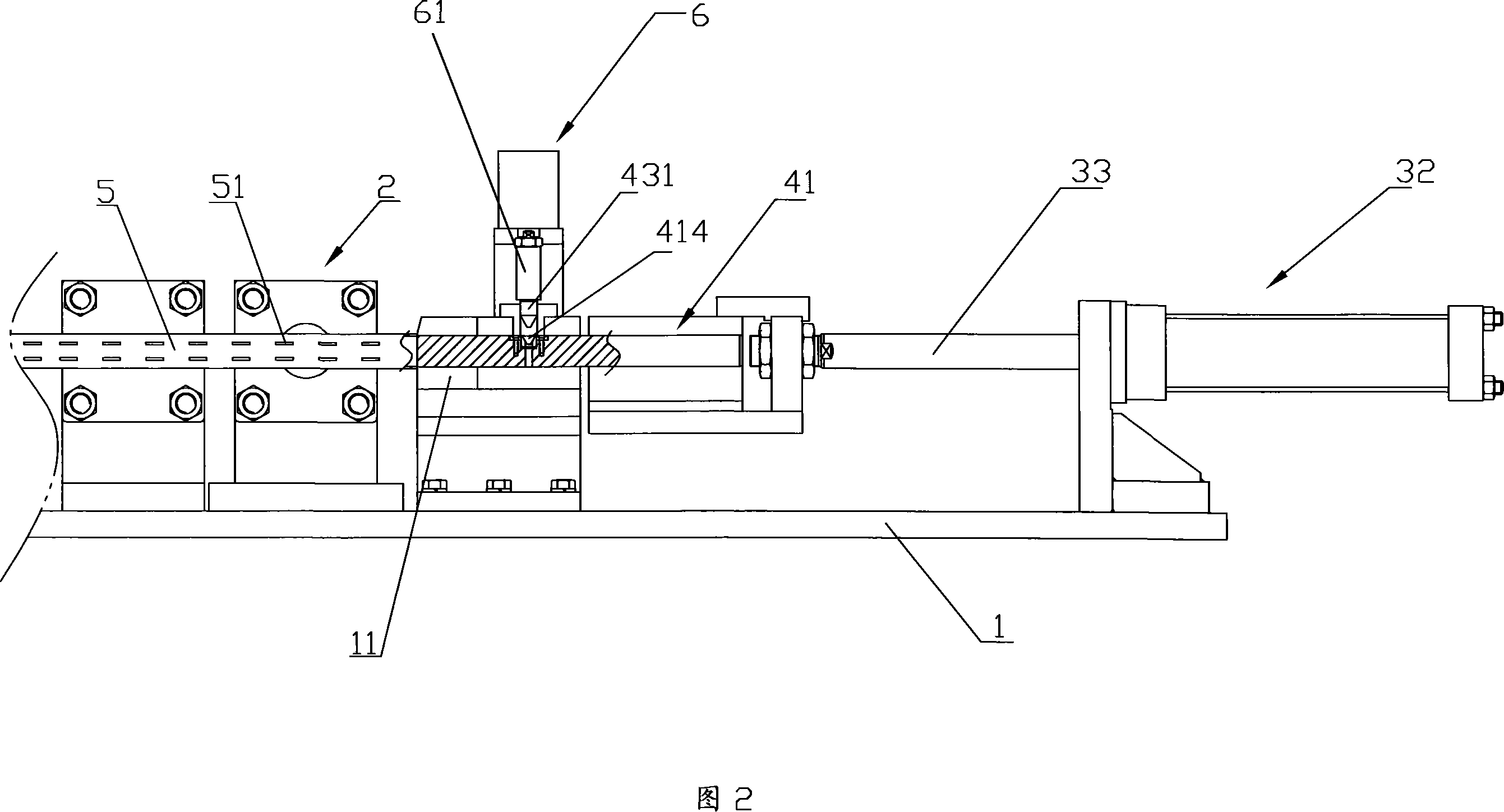
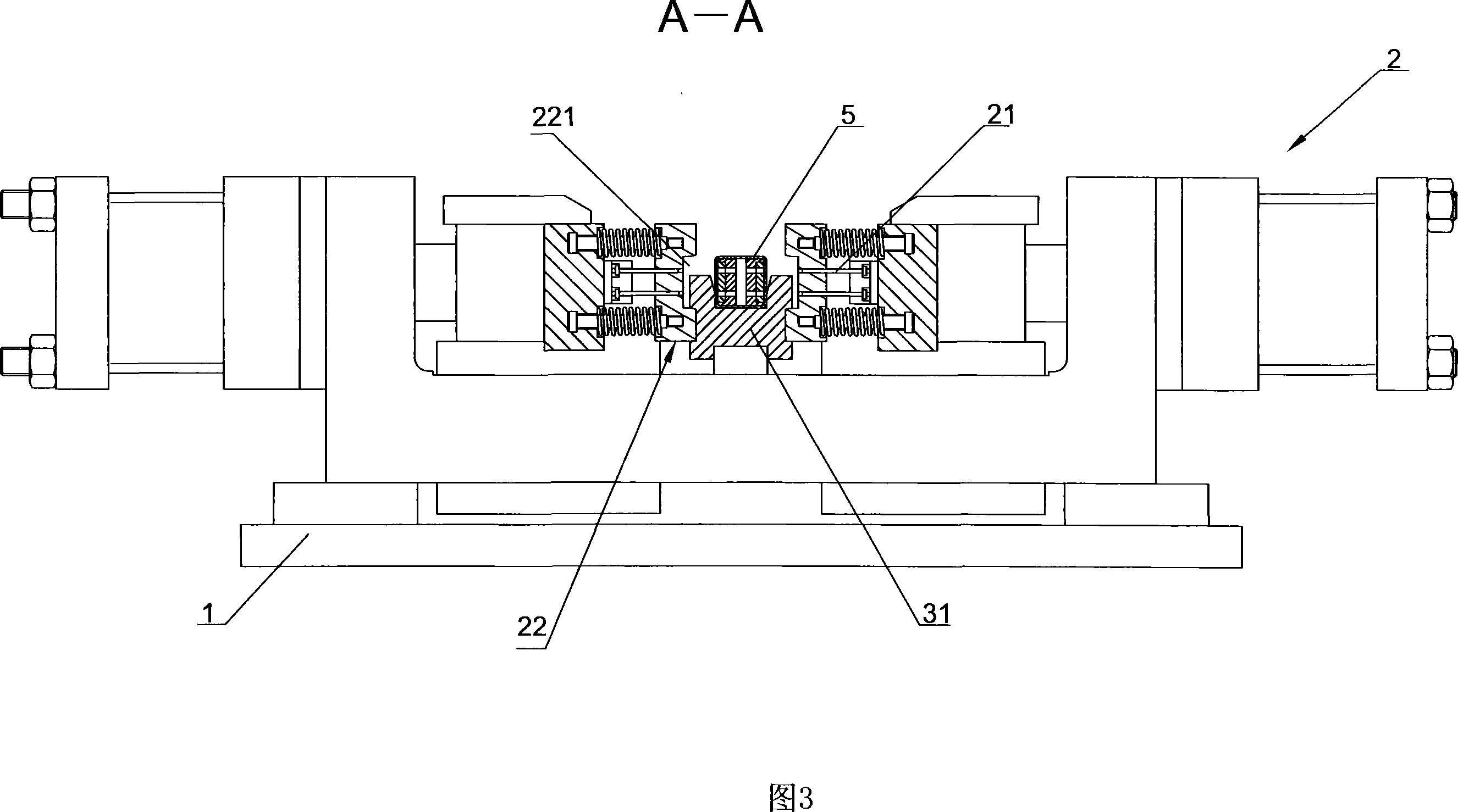
[0023] Referring to Figures 1 to 7, a square tube punching machine includes a frame 1, a plurality of tool holders oppositely arranged on both sides of the frame 1, a positioning mechanism for determining the punching position of a workpiece 5 4 and a clamping mechanism 3 for fixing the workpiece 5 to be processed in the axial direction. Each tool holder 2 is movably provided with a pair of punching pins 21 arranged up and down. When the workpiece 5 is fixed, it is located on the workpiece 5 The punching pins 21 on both sides of the punching needles are punched simultaneously, and the processing can be completed after two punching. The "upper" and "lower" positional relationships described in this specification correspond to the upper and lower positional relationships shown in FIG. 3.

[0024] Among them, the clamping mechanism 3 includes a bracket 31 arranged on the frame 1 for supporting the workpiece 5, clamping cylinders 32 respectively fixedly arranged on two opposite parts ...


PUM


Abstract

The present invention relates to a square pipe punching machine. It includes machine frame, several tool seats which are respectively oppositely-placed on two sides of said machine frame, positioning mechanism for defining punching position of workpiece and holding mechanism. On every tool seat a mobile punching needle is set, and the positioning mechanism includes a piercing rod which can be passed through the workpiece interior, in the middle portion of said piercing rod several positioning holes are cut, said several positioning holes are correspondent to the punching needles. Besides, said invention also provides the working principle of said square pipe punching machine and its concrete operation method.

Description

Technical field [0001] The invention relates to a device for processing square holes on square pipe fittings. Background technique [0002] It is widely used in square bracket tubes in supermarkets and shopping malls’ shelves or display racks. Usually, several square holes are processed along the length on the four outer surfaces of the square bracket tubes. The square tube punching machine in traditional technology includes For the tool holder of the through hole, a pair of punching needles are provided on the tool holder at the four walls of the through hole. When the workpiece to be processed passes through the through hole, the four pairs of punching needles move inward to complete a punching; the workpiece is in one position After punching the hole, the tool holder moves along the length of the workpiece to the next punching position for punching. [0003] When using traditional technology to punch pipe fittings, it is very easy to cause the outer wall of the pipe fitting to...

Claims


Application Information

Patent Timeline
IPC IPC(8): B21D28/28B21D28/34B21D28/36B26F1/00B26F1/24B26D7/01
Inventor 刘家真田中华
Owner 庄添财
Why Eureka
Try Eureka