Damper regulation mechanism of adjustable shock-absorber
A damping adjustment and shock absorber technology, applied in shock absorbers, shock absorbers, springs/shock absorbers, etc., can solve the problems of intensified foaming and aging, poor consistency of damping performance, and increased damping attenuation of shock absorbers. , to achieve the effect of saving production cost, stable working performance and light foaming degree
- Summary
- Abstract
- Description
- Claims
- Application Information
AI Technical Summary
Problems solved by technology
Method used
Image
Examples
Embodiment 1
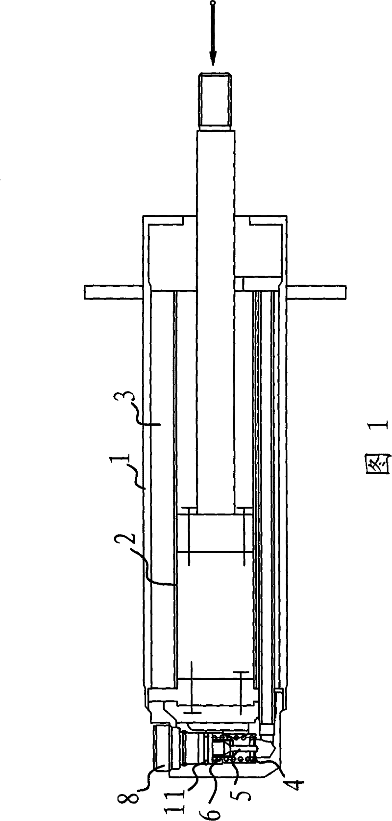
[0023] Such as figure 1 As shown, the damping adjustment mechanism of the adjustable shock absorber is set at the connection between the cylinder 2 and the oil storage chamber 3 between the outer cylinder 1 and the cylinder 2, including the sealing valve plate 4, the valve core 5, the spring 6, etc. . In this embodiment, the oil storage chamber 3 is an annular space between the outer cylinder 1 and the cylinder 2 .
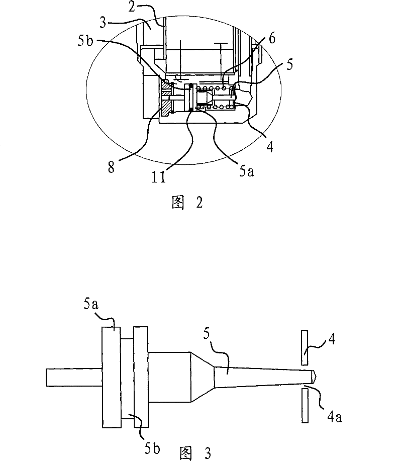
[0024] Such as figure 2 As shown, the sealing valve plate 4 is fixed at the communication place between the cylinder barrel 2 and the oil storage chamber 3 . More specifically, the sealing valve plate 4 is fixed on the bottom of the cylinder barrel 2, and there is a normally open gap between the sealing valve plate 4 and the valve core 5 for hydraulic oil to pass through. The sealing valve plate 4 here does not completely seal the connection between the cylinder barrel 2 and the oil storage chamber 3, and the hydraulic oil can pass through the oil passage, the...
Embodiment 2
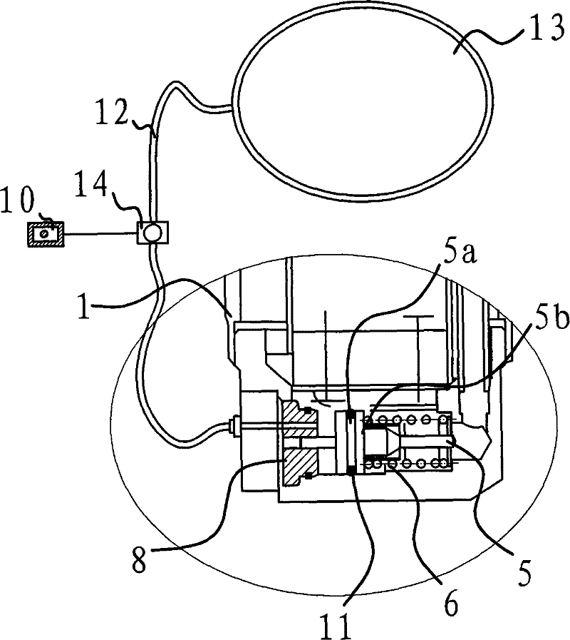
[0029] In this example, if Figure 5As shown, the valve seat 8 is pierced with an air guide tube 12 for applying air pressure to the baffle plate 5a on the valve core 5, the air guide tube 12 is connected with the air supply pump 9, and an air pressure regulator 14 is also provided on the air guide tube 12 . The driver can also control or preset the air pressure regulator 14 through the controller 10, thereby controlling the operation of the air supply pump 9, so that the air pressure received by the baffle plate 5a changes, and then changes the air pressure between the valve core 5 and the sealing valve plate 4. Positional relationship. The rest are similar to those in Example 1, and will not be described in detail herein.
Embodiment 3
[0031] In this example, if Figure 6 As shown, the spool 5 leans against an adjusting knob 7 for adjusting the relative position between the spool 5 and the sealing valve plate 4, and the adjusting knob 7 is threadedly connected to the bottom of the outer cylinder 1. When the adjusting knob 7 is turned, the positional relationship between the valve core 6 and the sealing valve plate 4 can be changed. Therefore, the damping value can be adjusted conveniently by turning the adjusting knob 7 .
PUM
 Abstract
Description
Claims
Application Information
 - R&D
- Intellectual Property
- Life Sciences
- Materials
- Tech Scout
- Unparalleled Data Quality
- Higher Quality Content
- 60% Fewer Hallucinations
Browse by: Latest US Patents, China's latest patents, Technical Efficacy Thesaurus, Application Domain, Technology Topic, Popular Technical Reports.
© 2025 PatSnap. All rights reserved.Legal|Privacy policy|Modern Slavery Act Transparency Statement|Sitemap|About US| Contact US: help@patsnap.com


