Automatic mobile target tracking and shooting method

A moving target, automatic tracking technology, applied in the field of video surveillance, can solve the problems of inaccurate identification and capture, low capture speed, etc., to achieve the effect of increasing intelligence and controllability

Inactive Publication Date: 2007-11-14
深圳市融合视讯科技有限公司
View PDF0 Cites 59 Cited by
  • Summary
  • Abstract
  • Description
  • Claims
  • Application Information

AI Technical Summary

Problems solved by technology

This kind of camera has a relatively simple structure, but it captures by recognizing the facial features of people. Due to the complex facial features of pe...

Method used


Image

  • Automatic mobile target tracking and shooting method

Examples


Embodiment 1

[0021] Example 1: Tracking and shooting of moving targets with dual cameras

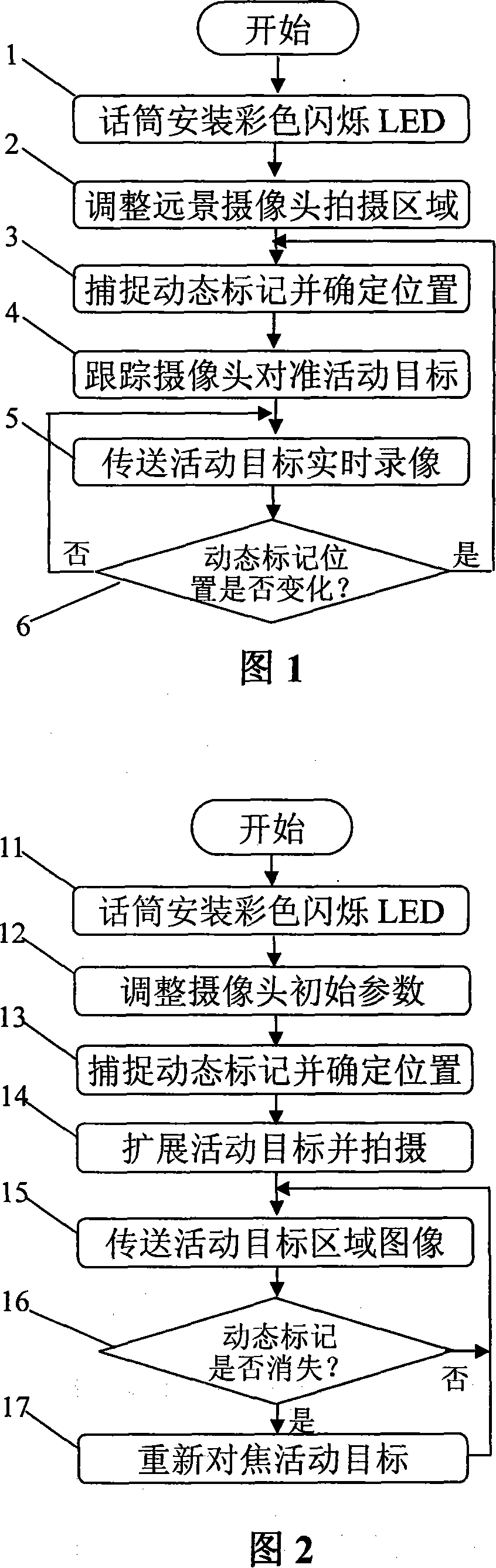
[0022] See Figure 1 of the accompanying drawing in the manual. The dual-camera tracking and shooting of moving targets is in the meeting room. A panoramic camera is installed to aim at the rostrum, and the shooting area of ​​the panoramic camera (marked 2 in Figure 1) is adjusted so that the shooting range of the panoramic camera is just right. Cover all speakers on the entire podium, and keep the camera fixed in the future. In addition, a tracking camera with two degrees of freedom is installed next to the panoramic camera, and the coverage of the camera is a close-up image of the upper body of the speaker. When the meeting starts, the host of the meeting hands over the microphone to the speaker on the rostrum. After the speaker turns on the microphone and starts to speak, the LED on the microphone starts to flash, and the panoramic camera can capture the dynamic picture of the entire rostrum. Dyna...

Embodiment 2

[0029] Embodiment 2: Digital processing and display of moving targets with a single camera

[0030] This embodiment does not have accompanying drawing, just carry out digital processing to the picture that panoramic camera is taken by computer, identify the area that has dynamic mark from the whole dynamic picture of shooting, this area is exactly the dynamic image of speaker, and this area is amplified and displayed That's it. If the position of the dynamic marker changes, the new speaker can be relocated and the area where it is located can be zoomed in. Since the image quality may be reduced after zooming in, a high-resolution camera and image processing technology can be used to achieve satisfactory results. This method is relatively simple, low in implementation cost, and can be fully automated.

Embodiment 3

[0031] Embodiment 3: Tracking and shooting of moving targets with a single camera

[0032] See Fig. 2 of the accompanying drawing in the specification, using the same conference site as in Embodiment 1, only using one camera, which has a telescopic lens in addition to dual-degree-of-freedom rotation, and can perform optical zoom of two multiples. The initial position of the camera is equivalent to a panoramic camera and aimed at the rostrum, and its initial parameters (marked 12 in Figure 2) are adjusted in advance, so that the initial shooting range of the camera just covers all the speakers on the entire rostrum. In addition, after the camera is zoomed, its camera coverage is a close-up image of the upper body of the speaker. When the meeting starts, the host of the meeting hands the microphone to the speaker on the rostrum. After the speaker turns on the microphone and starts to speak, the LED on the microphone starts to flash, and the dynamic picture of the entire rostrum ...


PUM


Abstract

The method includes following steps: cyclic variational dynamic markers recognizable to computer image system are installed on moving targets; based on realtime graphic shot by panorama pick-up head, image analysis module finds out position data in coordinates of dynamic markers in whole image, and sends the data to the capture module for moving target; the capture module calculates specific positions of the dynamic markers within range of panorama pick-up head, as well as controls rotation of tracking pick-up head; thus, shooting focus aims at specific positions of the dynamic markers in realtime; sending images of the dynamic markers taken in realtime to pointed monitor for display. Using current equipment, the invention increases intelligence and controllability. Moreover, ordinary user can install system by self to monitor dynamic object expediently without need of help from specialized technical personnel.

Description

technical field [0001] The invention relates to the field of video surveillance, in particular to a method for automatically tracking and photographing a moving target in real time. Background technique [0002] Some of the existing automatic tracking cameras are equipped with passive infrared receivers on the camera, and the passive infrared receivers are respectively connected to an independent signal amplification circuit, the signal amplification circuit is connected to a driving circuit, and the driving circuit is connected to at least one driving motor , the driving motor is arranged in a supporting frame driving mechanism. When the moving object being photographed appears within the receiving range of the infrared receiving tube, the infrared rays are reflected back to the infrared receiving tube. When the moving object continues to move, multiple set monitoring points return signals respectively, which can judge the movement of the target object Direction, and then ...

Claims


Application Information

Patent Timeline
IPC IPC(8): H04N7/18G06T7/20
Inventor 赵忠华
Owner 深圳市融合视讯科技有限公司
Why Eureka
Try Eureka