Dynamic loading motor speed regulation experiment method and system based on signal flow diagram

A technology of dynamic loading and motor speed regulation, which is applied in the direction of motor generator testing, etc., can solve the problems of increasing repeated experiments, high preparation time cost, and high experiment cost, so as to reduce design difficulty and experiment risk, facilitate maintenance and management, and experiment The effect of simple process

Pending Publication Date: 2021-08-17
INNER MONGOLIA UNIV FOR THE NATITIES
View PDF12 Cites 0 Cited by
  • Summary
  • Abstract
  • Description
  • Claims
  • Application Information

AI Technical Summary

Problems solved by technology

[0003] In specific operations, there are mainly two types of schemes. One is to customize the automated experimental method according to the needs. This method is a customized method that requires long-term planning to avoid errors in a certain link, which will cause the preparation time cost in the early stage. Higher will also increase the difficulty of the experiment; the other is to decompose the existing requirements and use a variety of simple methods to conduct experiments. This method is a decomposition method, which will greatly increase the uncertainty of the experiment due to the accumulation of various links sex
In addition, in the above two schemes, the amount of manual input is difficult to predict. Although increasing the amount of manual input is conducive to ensuring the safety of the experiment and reducing the risk of the experiment, the artificial response ability is limited after all, and there is a shortcoming of insufficient timeliness. At the same time, if the artificial Excessive investment will greatly increase the possibility of repeated experiments, so as to increase the cost of experiments
[0004] In summary, the traditional motor speed control experiment method is difficult to balance the relationship between experiment risk, experiment cost and experiment efficiency, and there are technical problems of high experiment risk, high experiment cost and low experiment efficiency.

Method used


Image

  • Dynamic loading motor speed regulation experiment method and system based on signal flow diagram
  • Dynamic loading motor speed regulation experiment method and system based on signal flow diagram
  • Dynamic loading motor speed regulation experiment method and system based on signal flow diagram

Examples


Embodiment Construction

[0042] In order to make the purpose, technical solution and advantages of the present invention clearer, the technical solution of the present invention will be described in detail below. Apparently, the described embodiments are only some of the embodiments of the present invention, but not all of them. Based on the embodiments of the present invention, all other implementations obtained by persons of ordinary skill in the art without making creative efforts fall within the protection scope of the present invention.

[0043] Below in conjunction with accompanying drawing and specific embodiment the present invention is described in further detail:

[0044] The specific embodiment of the motor speed regulation experimental system based on the dynamic loading of the signal flow diagram provided by the present invention:

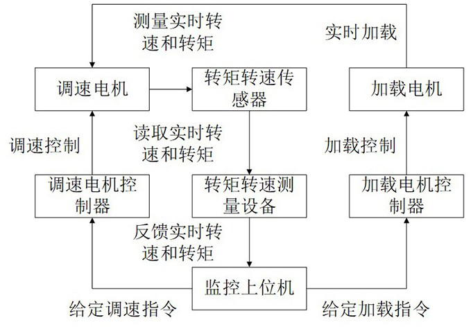
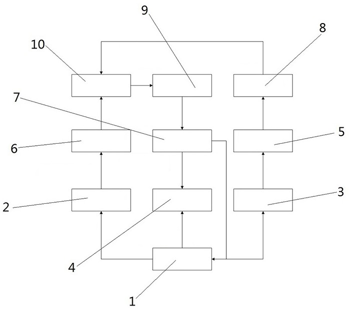
[0045] Such as figure 2 and image 3 As shown, the dynamically loaded motor speed regulation experimental system based on the signal flow diagram includes...


PUM


Abstract

The invention relates to the technical field of motor speed regulation experiments, in particular to a dynamic loading motor speed regulation experiment method and system based on a signal flow diagram. The system comprises a signal flow management center, an adjustable-speed motor monitor, a dynamic loading monitor, a graphic data grabber, an adjustable-speed motor controller, a loading motor controller and a torque and rotating speed measuring device. The experiment risk can be reduced, the experiment cost is saved, and the experiment efficiency is improved. Therefore, breakthrough of a core algorithm is promoted, test efficiency is improved, development risks are reduced, online time is shortened, and development cost is saved.

Description

technical field [0001] The invention relates to the technical field of motor speed regulation experiments, in particular to a method and system for motor speed regulation experiments based on dynamic loading of signal flow diagrams. Background technique [0002] The traditional motor speed regulation experiment is carried out in the way of dynamic loading, and its structure diagram is as follows: figure 1 As shown, the speed regulation motor adopts the speed regulation control algorithm embedded in the core chip of the speed regulation motor controller to implement speed regulation control to achieve the purpose of real-time speed regulation; the loading motor uses the loading control algorithm embedded in the core chip of the load motor controller to implement Loading control to make the speed regulating motor obtain a given motor load in real time; the torque speed sensor is used to measure the torque and speed of the speed regulating motor in real time, and its supporting...

Claims


Application Information

Patent Timeline
Patent Type & Authority Applications(China)
IPC IPC(8): G01R31/34
CPCG01R31/34
Inventor 刘罡王龙达
Owner INNER MONGOLIA UNIV FOR THE NATITIES
Why Eureka
Try Eureka