

Optical device with fresnel structure
A Fresnel structure, optical device technology, applied in optical components, optics, nonlinear optics, etc., can solve problems such as inability to achieve the effect of simplifying the manufacturing process
- Summary
- Abstract
- Description
- Claims
- Application Information
AI Technical Summary
Problems solved by technology
Method used
Image

Examples
Embodiment Construction
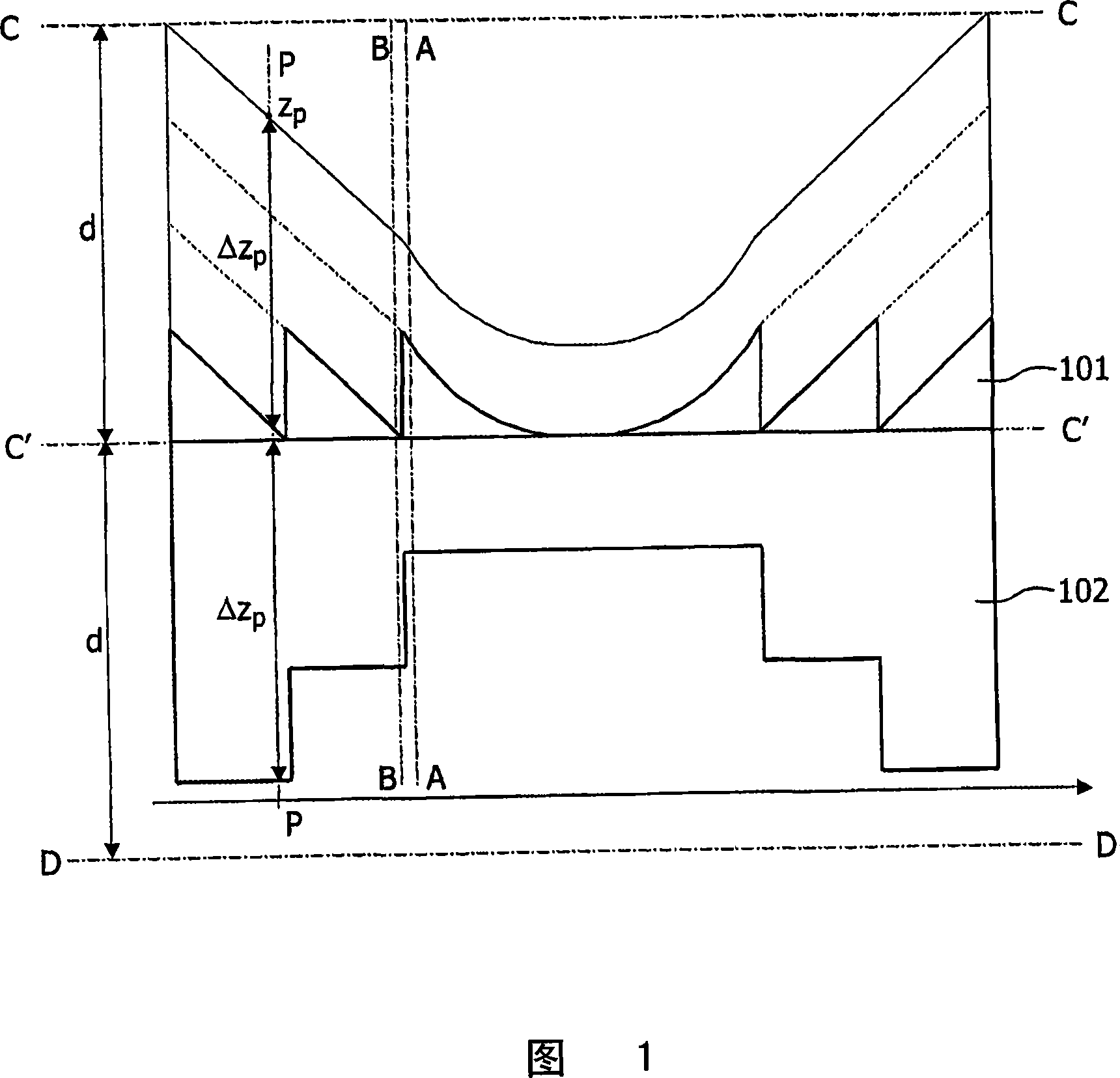
[0024] An optical device according to the invention is depicted in FIG. 1 . The optical device includes a Fresnel structure 101 and a stepped structure 102 . Fresnel structures are well known to those skilled in the art. For example, Fresnel lenses are described in J.J.M. Braat, "Microscope Objectives for Optical Disk Systems", Proceedings of the International Conference on "Theory and Applications of the 'Huygens' Principle 1690-1990", (TheHague / Scheveningen , 1990, Elsevier Science Publishers B.V.), editors: H.Blok, H.A.Ferweda, H.K.Kuiken, pp. 33-63. In FIG. 1 , conventional lenses used to make the Fresnel structure 101 are shown with thin lines, while the Fresnel structure 101 and the stepped structure 102 are shown with thick lines. Portions of the conventional lens that have been removed to make the Fresnel structure 101 are shown in dashed lines.
[0025] In Fig. 1, the Fresnel structure 101 and the stepped structure 102 are shown as distinct components. Nevertheles...
PUM
 Abstract
Description
Claims
Application Information