Three-dimensional pipe cutter

A pipe cutting machine, three-dimensional technology, applied in the direction of pipe shearing device, shearing device, accessories of shearing machine, etc., can solve the problems of affecting assembly, inconvenient adjustment, polluting the environment, etc., and achieve the effect of convenient adjustment

Inactive Publication Date: 2007-11-21
庄添财
View PDF0 Cites 40 Cited by
  • Summary
  • Abstract
  • Description
  • Claims
  • Application Information

AI Technical Summary

Problems solved by technology

When cutting the end of the pipe, only the clamping device drives the pipe to feed along a straight line, while the working position of the cutter does not move. This kind of pipe cutting machine cannot process various inclination angles, especially for non-cylindrical Special-shaped pipe fittings can only be processed by punching or gas cutting
Gas cutting not only pollutes the environment, but also has poor precision. Punching will easily deform the pipe fittings and affect subsequent assembly; or disassemble the tool holder, and then reinstall and fix it after adjusting the cutting angle, which is inconvenient to adjust

Method used


Image

  • Three-dimensional pipe cutter
  • Three-dimensional pipe cutter
  • Three-dimensional pipe cutter

Examples


Embodiment Construction

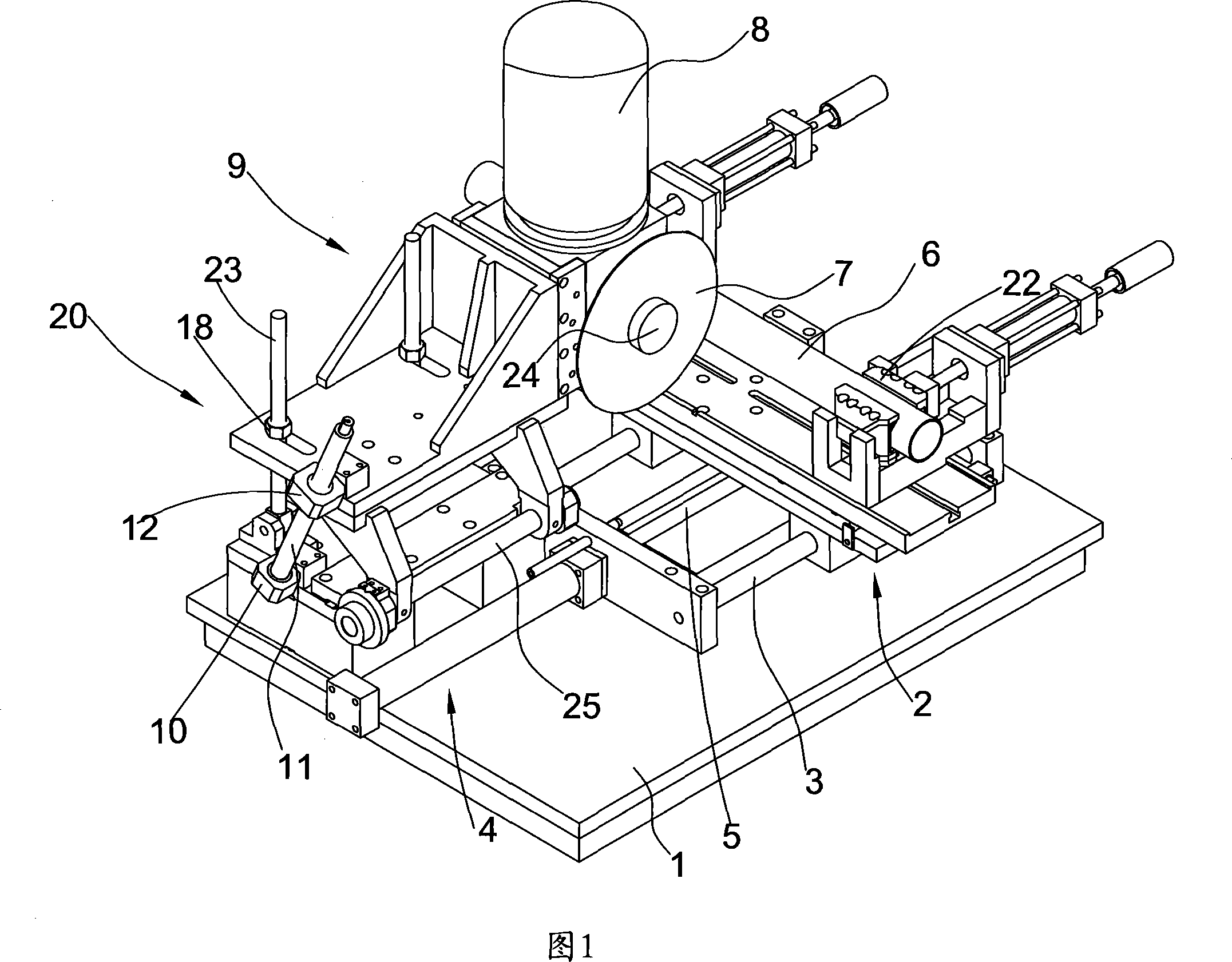
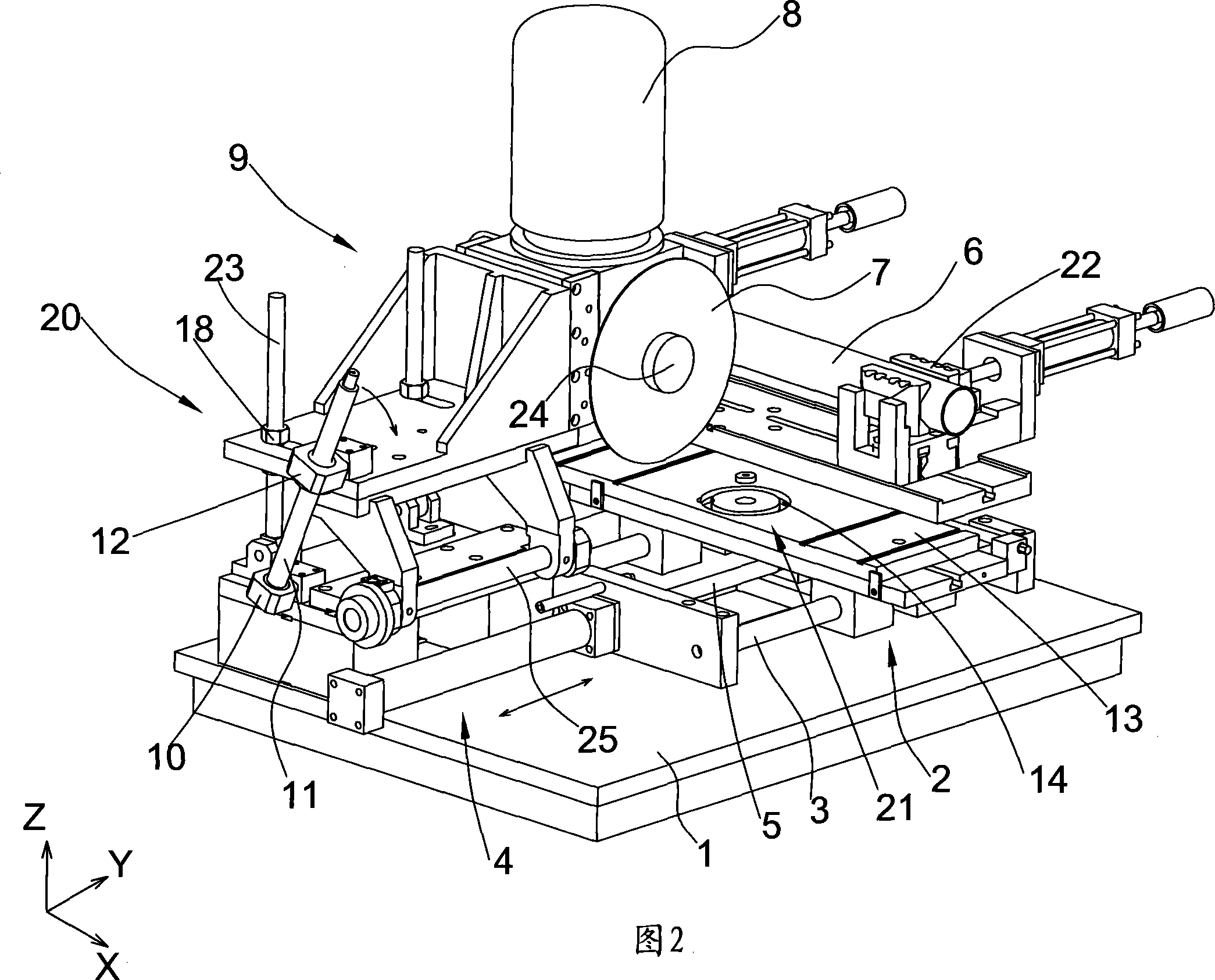
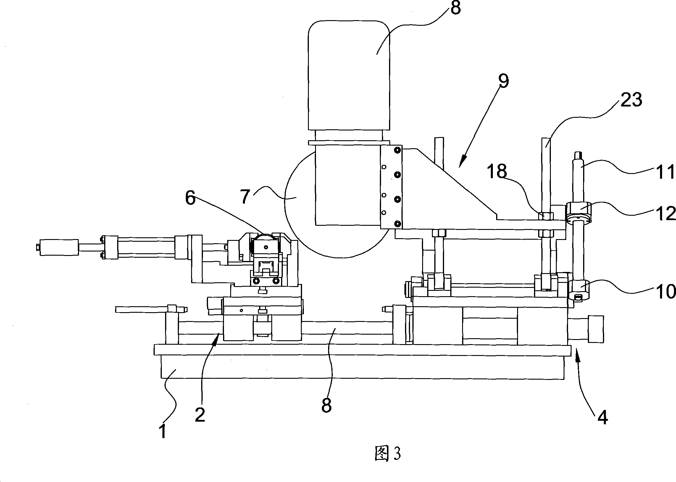
[0018] Referring to accompanying drawings 1 to 5, a three-dimensional pipe cutting machine includes a frame 1, a clamping device 2 for fixing a pipe 6 to be processed, a tool set on the frame 1 and a tool 7 is installed The fixed seat 9 is rotatably provided with a first rotating shaft 24 extending along the X-axis direction on the tool fixing seat 9, and the tool 7 is fixedly connected to the first rotating shaft 24; the frame 1 has a guide rail 3 extending in the horizontal direction, and the clip The holding device 2 is slidably arranged on the guide rail 3. The frame 1 has a second rotating shaft 25 extending along the direction of the Y axis perpendicular to the X axis. The tool holder 9 is rotatably connected to the second rotating shaft 25, and the tool is fixed A first locking device 20 is also provided between the seat 9 and the frame 1 so that the tool fixing seat 9 and the frame 1 are relatively fixed. When the first locking device 20 is in a locked state, the tool f...


PUM


Abstract

The invention is concerned with a kind of three-dimensional machine to cut pipe, relating to machine rack, holding equipment, fixing seat for drill. The drill connects with the fixing seat in moving, and the holding equipment sets on the machine rack in sliding. The drill connects on the first running axis extending to the axis of X and the machine rack has guiding rail extending along the level direction and the holding equipment set on this guiding rail in sliding. The machine rack has the second running axis extending along the axis of Y that being upright to axis of X and the drill seat connects with the second running axis in sliding. There is the first lock equipment between the drill fixing equipment and machine rack, and the holding equipment relates to the sliding seat connecting with guiding rail and worktable on the sliding seat moving around the axis of Z, and the sliding seat and worktable can match and slide with each other and there is the second lock equipment between the sliding seat and worktable. The three-dimensional relationship between the drill and pipe piece to cut the pipe piece from multi-angle, and the adjustment is easy to cut the strange shape of pipe piece or cut for many times.

Description

technical field [0001] The invention relates to a three-dimensional pipe cutting machine, which belongs to the category of pipe fitting cutting machines. Background technique [0002] Generally, when cutting or trimming metal pipe fittings widely used in industrial fields such as machinery and construction, it is mainly through gas cutting or machine tool processing. The pipe cutting machine in the prior art usually includes a frame, a clamping device for fixing the pipe to be processed, and a tool holder fixedly arranged on the frame, and the tool is rotatably connected to the tool holder , the clamping device is movably arranged on the frame. When cutting the end of the pipe, only the clamping device drives the pipe to feed along a straight line, while the working position of the cutter does not move. This kind of pipe cutting machine cannot process various inclination angles, especially for non-cylindrical Special-shaped pipe fittings can only be...

Claims


Application Information

Patent Timeline
Patent Type & Authority Applications(China)
IPC IPC(8): B23D21/00B23D21/02B23D33/02B23D35/00B23D36/00B26D3/00B26D1/143B26D7/26B26D7/01B26D7/00
Inventor 李卫峰丁雷敏
Owner 庄添财
Why Eureka
Try Eureka