Substrate transportation method and apparatus

一种基板搬送、基板的技术,应用在清洁方法和用具、运输和包装、化学仪器和方法等方向,能够解决复杂、去除异物、昂贵等问题,达到紧凑结构、可能性小、低廉结构的效果

Inactive Publication Date: 2007-11-21
NEC CORP
View PDF5 Cites 20 Cited by
  • Summary
  • Abstract
  • Description
  • Claims
  • Application Information

AI Technical Summary

Problems solved by technology

[0008] However, the above-mentioned conventional techniques require relatively complex, bulky and expensive devices for removing dust or any other foreign matter from the bottom surface of the substrate.
It is also difficult to effectively remove foreign matter from substrates being conveyed

Method used


Image

  • Substrate transportation method and apparatus
  • Substrate transportation method and apparatus

Examples


Embodiment Construction

[0024] Now, the structure and operation of preferred embodiments of the substrate transfer method and apparatus according to the present invention will be described in detail with reference to the accompanying drawings.

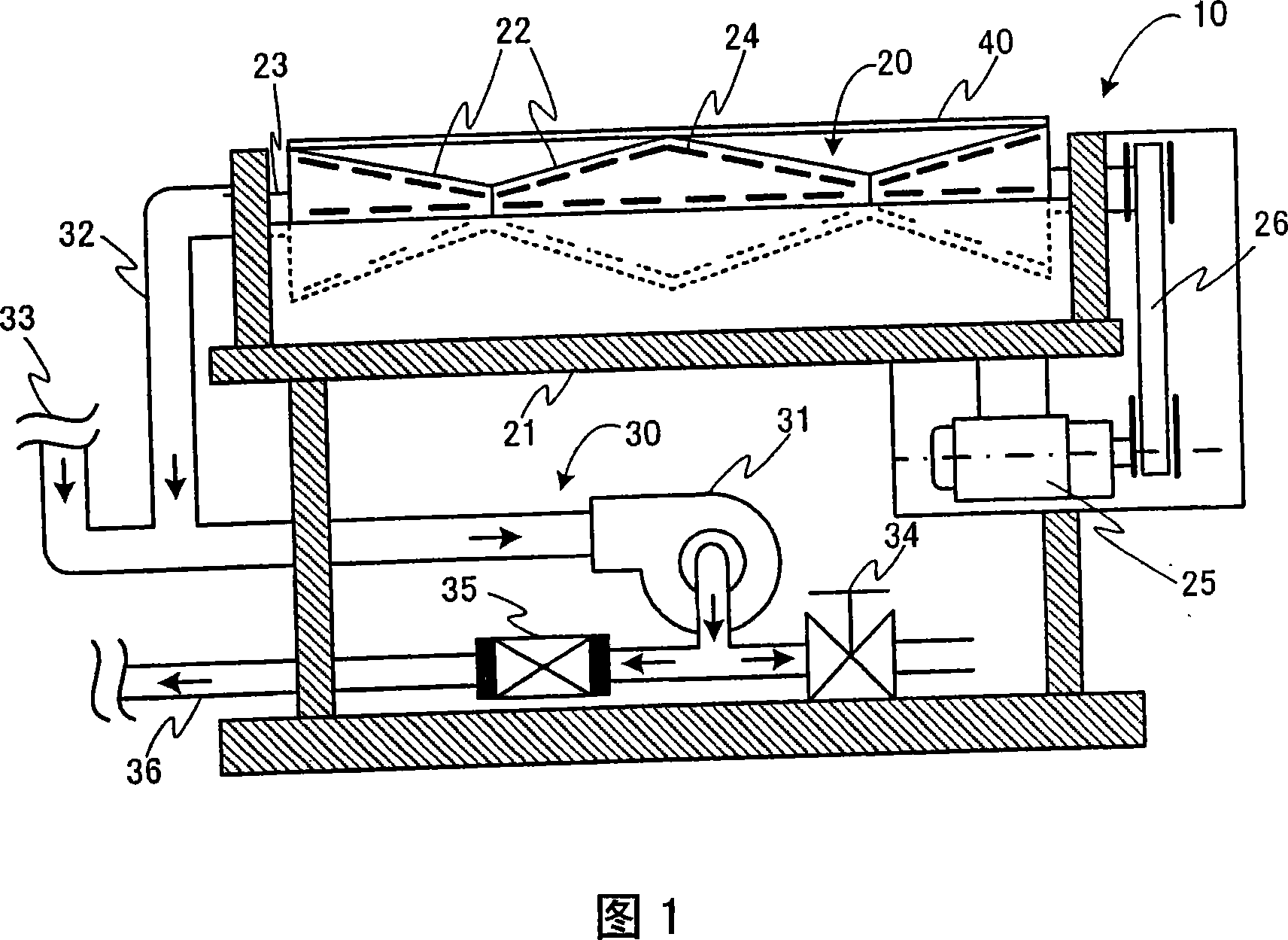
[0025] First, referring to FIG. 1, FIG. 1 illustrates a partial cutaway side view of a preferred embodiment of a substrate transfer device according to the present invention. The substrate transfer device 10 mainly includes a substrate transfer unit 20 and an air blowing / suction unit (hereinafter referred to as an air blowing / suction unit) 30 . As will be described in detail below, the substrate 40 , that is, a thin plate such as a glass substrate is conveyed in a direction perpendicular to the paper surface of FIG. 1 .

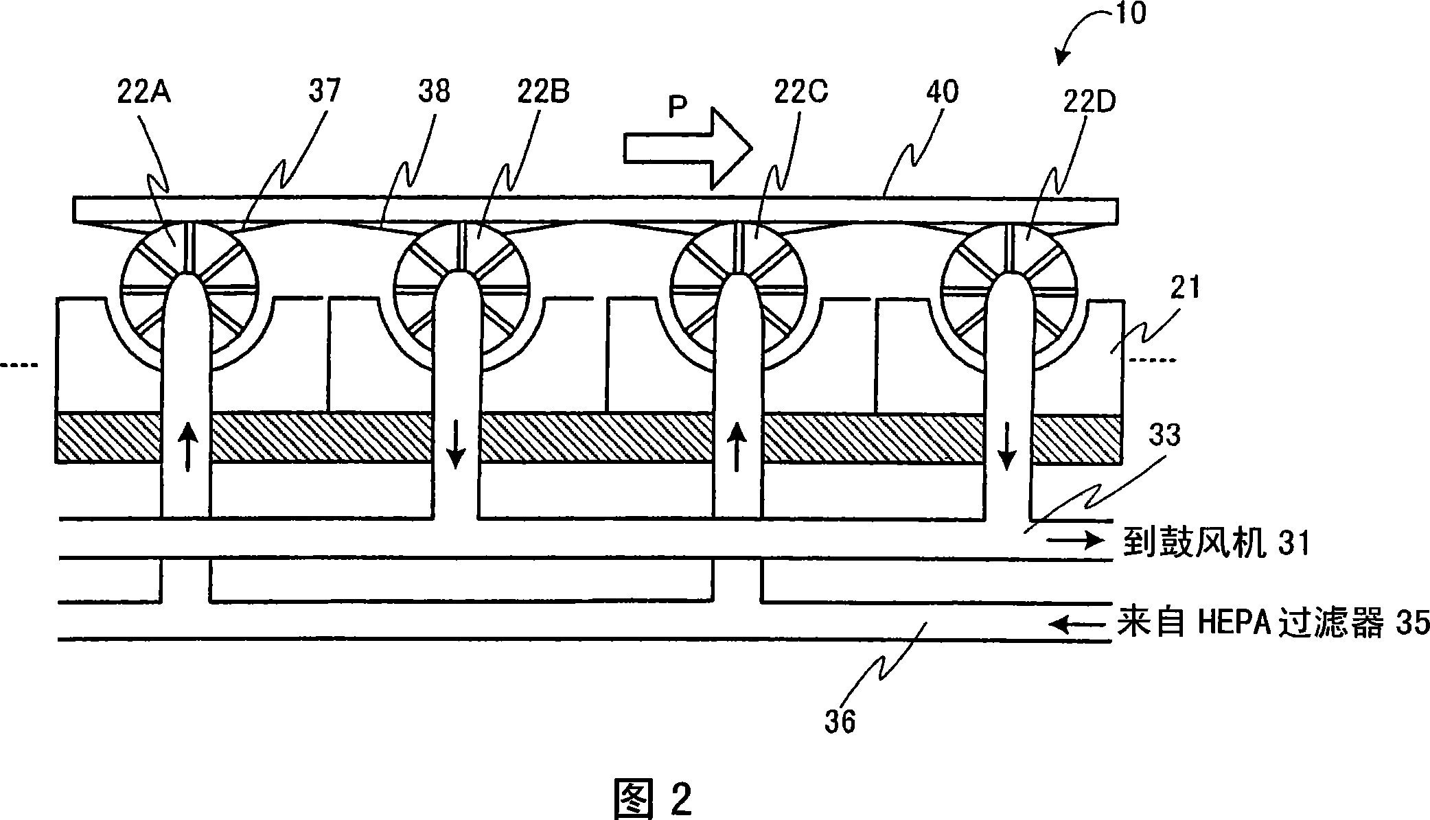
[0026] The substrate conveying section 20 includes a plurality of conveying rollers 22 through which respective rotating shafts 23 extend. Each rotating shaft 23 extends through both side walls of a frame (or block) 21 that covers the botto...


PUM


Abstract

The substrate transportation apparatus 10 comprises a plurality of transportation rollers 22 A- 22 D disposed at a predetermined spacing for transporting the substrate 40 in response to rotation of the transportation rollers 22. Each of the transportation rollers 22 is generally hollow cylindrical member formed with a plurality of slit nozzles 24 in the circumference. Alternating rows of the transportation rollers 22 are designed to blow and suck air to and from the bottom surface of the substrate 40 under transportation while preventing dust or any other foreign materials from collecting on the bottom surface of the substrate 40.

Description

[0001] This application claims priority from Japanese Patent Application No. 2006-137412 filed May 17, 2006, the entire contents of which are incorporated herein by reference. technical field [0002] The present invention relates to a substrate conveying method and device, more specifically, to a substrate conveying method and device, the substrate conveying method and device are used in the manufacture of electronic equipment (such as liquid crystal display panels LCD, semiconductor integrated device IC, etc.) A substrate such as a glass plate used in a substrate is transported from one location to another, and at the same time, dust or any other foreign matter adhering or accumulating on the back of the substrate is removed. [0003] The manufacture of electronic devices such as color liquid crystal display panels usually goes through a series of manufacturing steps such as masking, photolithography, etching, bonding, etc. These manufacturing steps are used to manufacture se...

Claims


Application Information

Patent Timeline
Patent Type & Authority Applications(China)
IPC IPC(8): B65G49/05B65G47/00B65G13/00B65G39/02B08B5/00G02F1/1333H01L21/677
CPCH01L21/67784
Inventor 长友和也
Owner NEC CORP
Why Eureka
Try Eureka