Composite hot pipe and its production

A manufacturing method and composite technology, applied in indirect heat exchangers, lighting and heating equipment, etc., can solve problems such as low yield rate, poor heat dissipation effect of electronic components, and performance degradation

Inactive Publication Date: 2007-11-21
FU ZHUN PRECISION IND SHENZHEN +1
View PDF0 Cites 11 Cited by
  • Summary
  • Abstract
  • Description
  • Claims
  • Application Information

AI Technical Summary

Problems solved by technology

The currently used capillary structure has a single type such as powder sintering type, groove type, fiber type or braided mesh type, but the steam flow path of the heat pipe with a single type of capillary structure will become unsmooth after being bent and flattened, and the capillary structure will also be damaged. will be destroyed, especially grooved heat pipes, and their performance will be greatly reduced
In order to solve the above problems, the industry adopts composite heat pipes in the design of heat pipes, such as combining the grooved capillary structure with the braided mesh capillary structure, as shown in Figure 1, which adds a floating heat pipe to the grooved capillary structure heat pipe. The woven mesh capillary structure is used to improve the incomplete capillary structure of the grooved heat pipe when it is bent and flattened and to increase its anti-gravity characteristics. However, because the added woven capillary structure cannot be fixed in place, the floating The braided capillary structure instead causes the steam flow path to be unsmooth, which in turn leads to the ineffective transmission of heat
It can be seen from the experimental results that when the floating braided capillary structure is randomly placed in the heat pipe, the production yield of the heat pipe will be low and the heat dissipation effect of the electronic components will be poor, which will affect the service life of the electronic components, especially after the heat pipe is bent and flattened. , its maximum heat transfer will be reduced by more than 50%

Method used


Image

  • Composite hot pipe and its production
  • Composite hot pipe and its production
  • Composite hot pipe and its production

Examples


Embodiment Construction

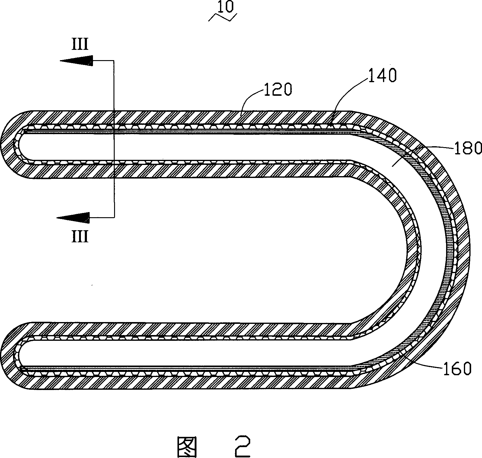
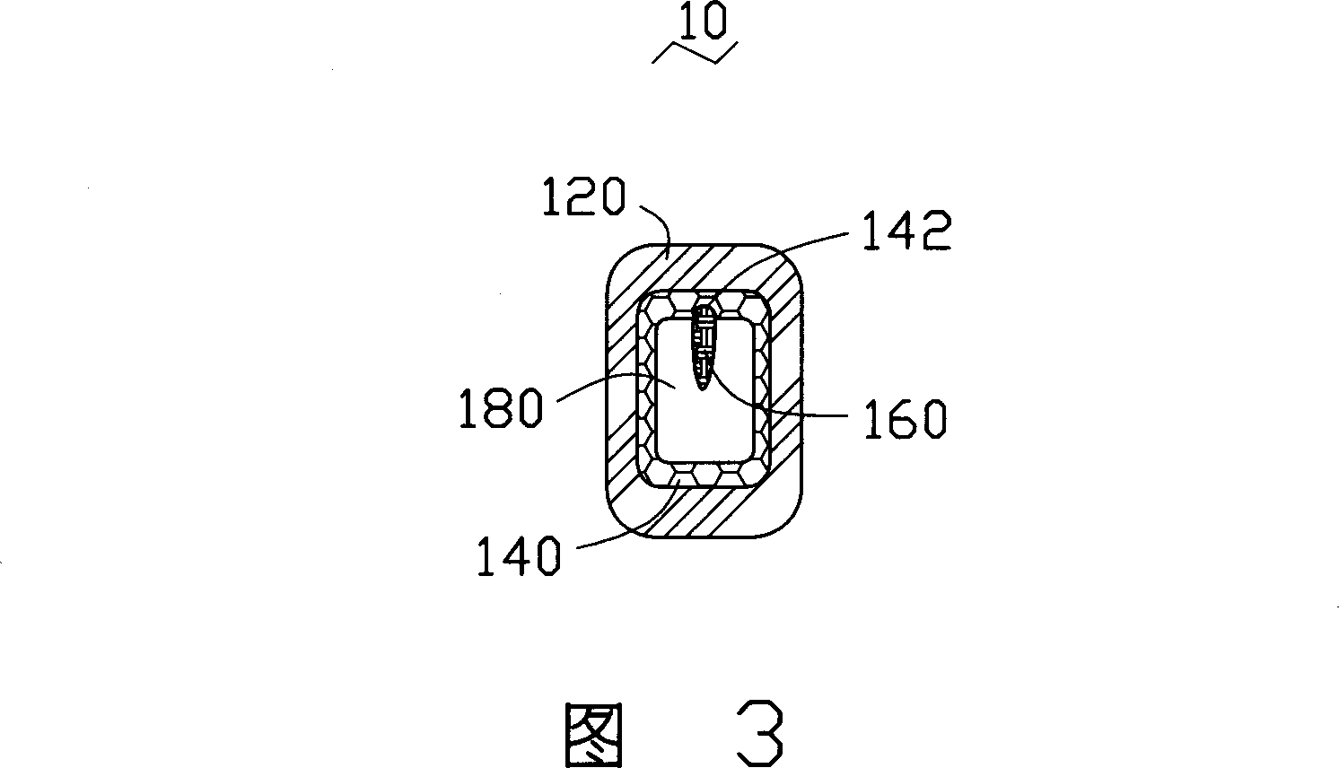
[0018] Please refer to FIG. 2 and FIG. 3 , which are longitudinal and transverse cross-sectional views of a composite heat pipe 10 according to an embodiment of the present invention. The heat pipe 10 is bent in a U shape, and its transverse section is rectangular. The heat pipe 10 includes a hollow shell 120, and a sintered first capillary structure 140 is attached to the inner wall of the hollow shell 120. The first capillary structure 140 in the heat pipe 10 is A groove 142 along the extension direction of the heat pipe 10 is provided on the inner surface close to the outer bend of the tube. A fibrous second capillary structure 160 is accommodated in the groove 142 and integrated with the first capillary structure 140 . At the same time, the center of the heat pipe 10 is surrounded by the inner surfaces of the capillary structures 140 and 160 to form a steam flow channel 180 arranged along the extending direction of the heat pipe 10, which contains a proper amount of working...


PUM


Abstract

The produce method of a complex heat pipe, it includes the process as flow, a) supplying a central rod with groove on the surface, b) supplying a second capillary structure which is in the groove, c) supplying a metal case, the rod with second capillary is in the case, d) the material of the first capillary filling in the room between the rod and case, e) baking the case until the first and second capillary into one part, f) drawing out the central rod, g) soldering the case, contracting the pipe, injecting, vacuuming and sealing. By the groove on the surface of the central rod, the capillary structure of the heat pipe has stable position, so this can not affect the transport of the steam in the pipe, and the capillary structure is whole, and it is suitable to transport the working fluid more quickly.

Description

technical field [0001] The invention relates to a heat transfer device, in particular to a composite heat pipe. Background technique [0002] Heat pipes are widely used for their ultra-quiet, high thermal conductivity, light weight, small size, no moving parts, simple structure and multi-purpose. layer, while the central space is in the state of an empty carcass, and an operating fluid equivalent to the total volume of pores in the capillary structure layer is injected into the vacuumed airtight tube. The currently used capillary structure has a single type such as powder sintering type, groove type, fiber type or braided mesh type, but the steam flow path of the heat pipe with a single type of capillary structure will become unsmooth after being bent and flattened, and the capillary structure will also be damaged. will be damaged, especially for grooved heat pipes, and their performance will be greatly reduced. In order to solve the above problems, the industry adopts com...

Claims


Application Information

Patent Timeline
Patent Type & Authority Applications(China)
IPC IPC(8): F28D15/04
CPCF28D15/046Y10T29/49895Y10T29/49384Y10T29/49353Y10T29/49377Y10T29/49361F28D15/0233
Inventor 侯春树林振辉
Owner FU ZHUN PRECISION IND SHENZHEN
Why Eureka
Try Eureka