
Method for measuring three-dimensional contour based on phase method

A technology of three-dimensional profile and measurement method, which is applied in the directions of measuring devices, photogrammetry/video metrology, surveying and navigation, etc., which can solve problems such as inability to guarantee calibration accuracy, affect system measurement accuracy, and cumbersome adjustment process, etc., to achieve construction Convenience and quickness, avoiding system errors, making simple effects

Inactive Publication Date: 2007-11-21
HAIAN COUNTY SHENLING ELECTRICAL APPLIANCE MFG +1
View PDF0 Cites 44 Cited by
  • Summary
  • Abstract
  • Description
  • Claims
  • Application Information

AI Technical Summary

Problems solved by technology

When calibrating the system, since the optical center is an imaginary spatial point and the optical axis is an imaginary spatial straight line, it is difficult to determine the specific position. The same is true for the projection center and projection axis. The above positional relationship is difficult to achieve in actual operation, resulting in The adjustment process during calibration is cumbersome, the calibration time is long, the operability is not good, and the calibration accuracy cannot be guaranteed, which in turn affects the measurement accuracy of the entire system

Method used


Image

  • Method for measuring three-dimensional contour based on phase method
  • Method for measuring three-dimensional contour based on phase method
  • Method for measuring three-dimensional contour based on phase method

Examples


Embodiment Construction

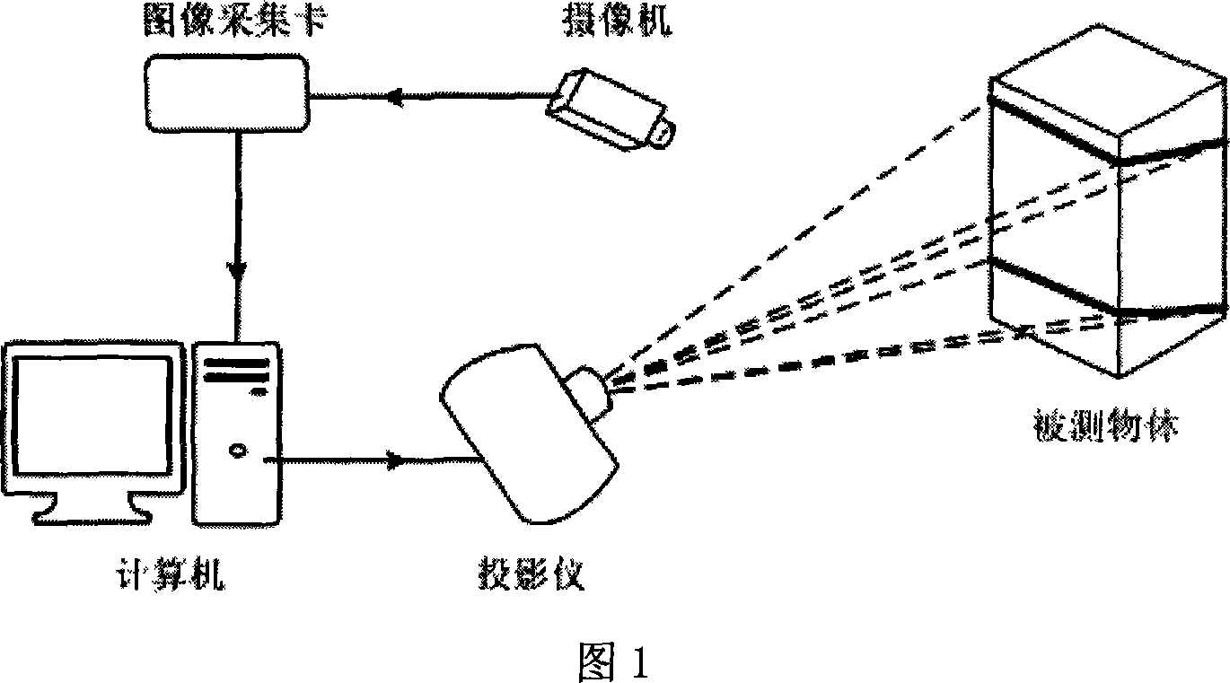
[0028] Below with reference to accompanying drawing, specific embodiment of the present invention is described in more detail:

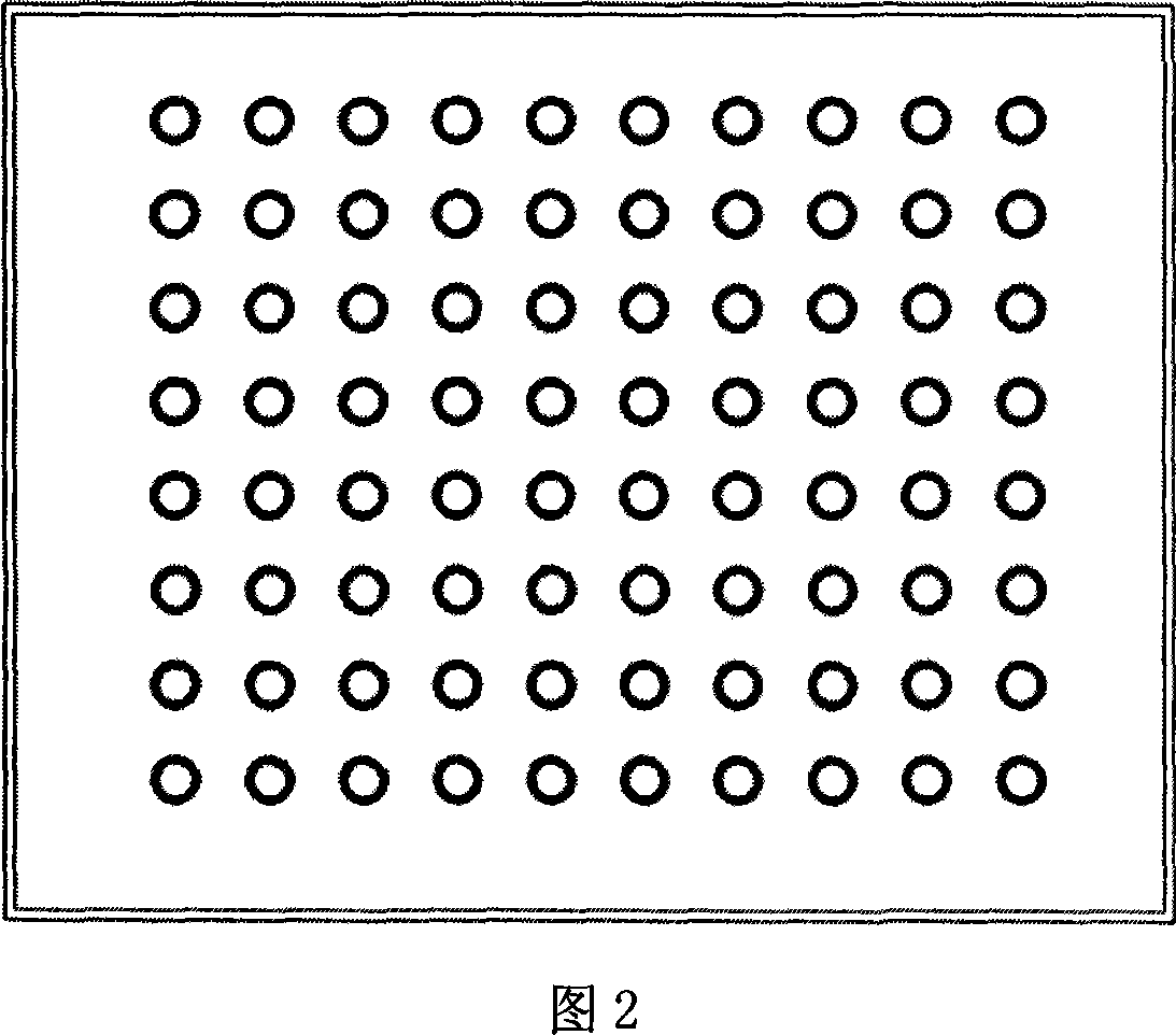
[0029] 1 and 2, the measurement system of the present invention includes a computer, a video camera connected to the computer through a graphics card, and a projection device (projector) and a calibration plate controlled by the computer. The positional relationship between the projection device and the camera is arbitrary, without any strict parallel, vertical or intersecting requirements, and there is no strict requirement for the position of the calibration plate during calibration. As shown in Figure 2, there are round mark points Q with known two-dimensional coordinates distributed on the calibration board i (i=1,2,...,k), its two-dimensional coordinates are (a i , b i ).

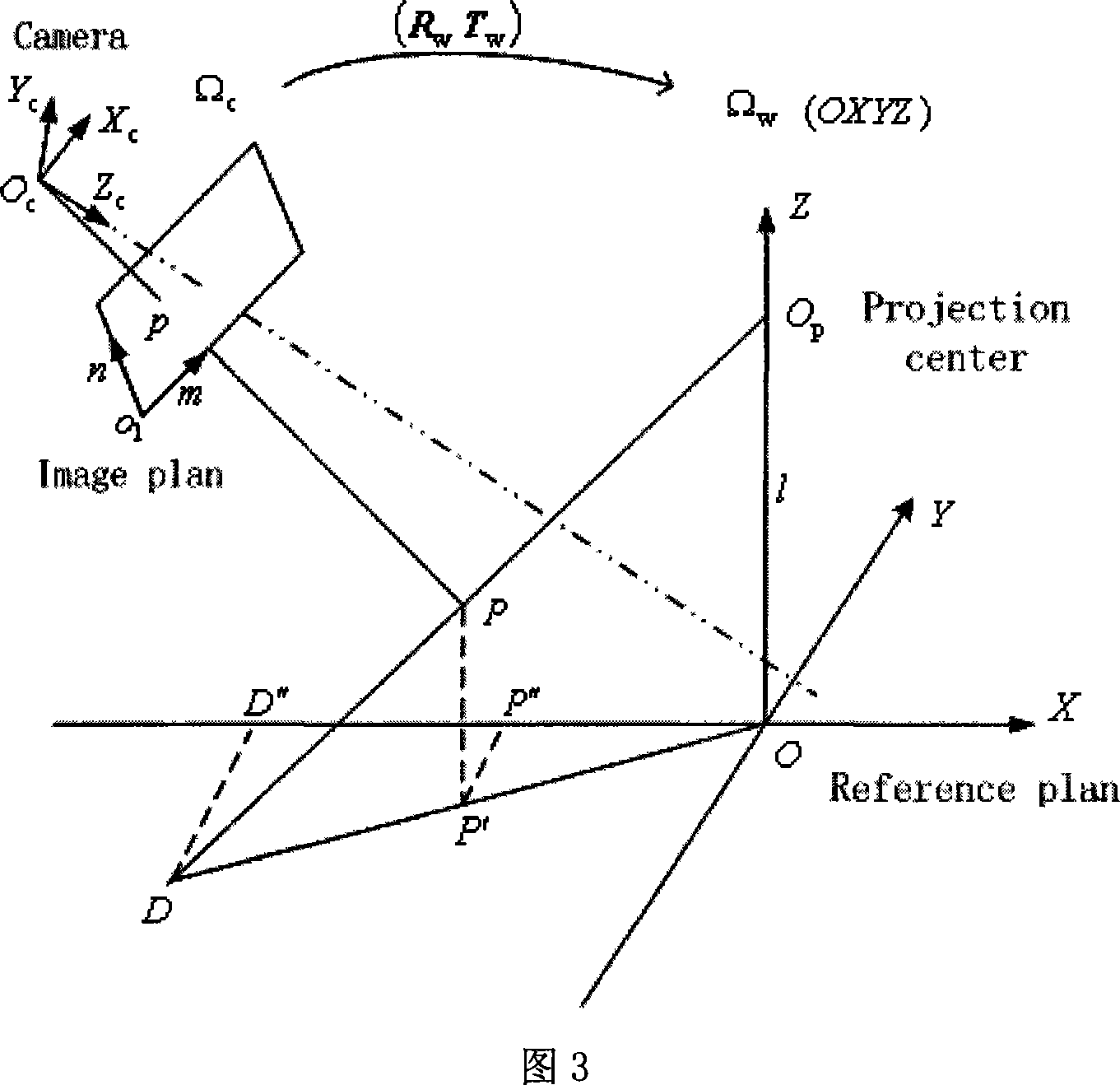
[0030] See Figure 3, Ω w , Ω c represent the reference coordinate system and the camera coordinate system respectively, and O P , O c denote the projection center and ...


PUM


Abstract

A 3-D outline measuring method based on phase includes calibrating internal parameter of video camera by applying nonlinear means, forming measurement system to cover required region of measured object by both projector and video camera simultaneously, setting up measurement relational expression (MRE) of formed measurement system, collecting sample points by placing calibration plate at 3-4 different positions in measurement scope, substituting obtained sample points into MRE to obtain system parameter, placing measured object in said measurement scope to obtain phase value being substituted in MRE and video camera model to obtain 3-D outline of object.

Description

technical field [0001] The invention relates to a system modeling and calibration method in which the relative positions of a camera and a projection device in a three-dimensional measurement system can be set arbitrarily, in particular to a three-dimensional contour measurement method based on a phase method. Background technique [0002] The optical three-dimensional object profile measurement technology obtains the three-dimensional information of the surface shape of the measured object by analyzing the image of the object. Among them, the phase profile measurement technology based on grating projection is not sensitive to the change of the surface reflectance of the object, has high measurement accuracy, and is easy to realize automatic measurement. It is a relatively representative three-dimensional measurement method. The measurement principle of the phase method is: a grating light field modulated by a periodic function is projected on the surface of the measured obj...

Claims


Application Information

Patent Timeline
Patent Type & Authority Applications(China)
IPC IPC(8): G01B11/24G01C11/00
Inventor 达飞鹏盖绍彦
Owner HAIAN COUNTY SHENLING ELECTRICAL APPLIANCE MFG
Learn More