Method for synchronizing time based on lock phase ring in wireless sensor network

A wireless sensor, time synchronization technology, applied in the direction of synchronization devices, transmission systems, digital transmission systems, etc., can solve the problem of large overhead, large algorithm space complexity, unable to give the optimal estimation of relative drift and relative offset, etc. question

A wireless sensor, time synchronization technology, applied in the direction of synchronization devices, transmission systems, digital transmission systems, etc., can solve the problem of large overhead, large algorithm space complexity, unable to give the optimal estimation of relative drift and relative offset, etc. question

CN101075862AInactive Publication Date: 2007-11-21TSINGHUA UNIV

Image

  • Method for synchronizing time based on lock phase ring in wireless sensor network
  • Method for synchronizing time based on lock phase ring in wireless sensor network
  • Method for synchronizing time based on lock phase ring in wireless sensor network

Examples


Embodiment Construction

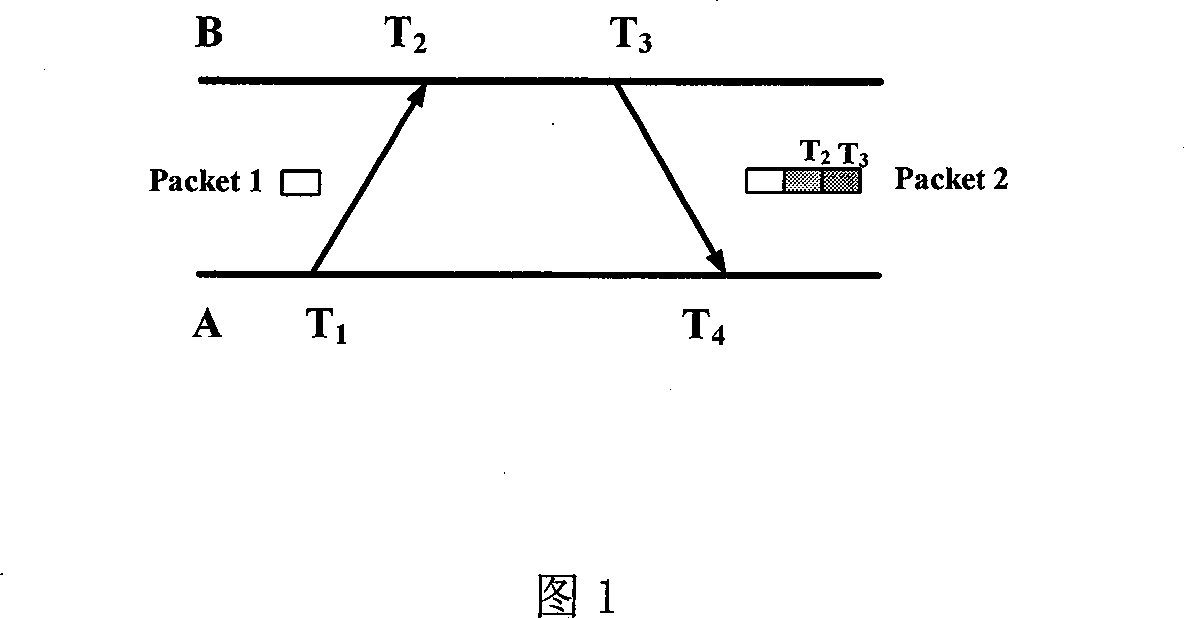
[0069] Considering the characteristics of dynamic topology changes in wireless sensor networks due to factors such as node and link failures, and the impact of systematic optimization of energy consumption such as topology control on the network in order to balance energy consumption and prolong the network life cycle, We continue to use the "root node" selection and maintenance scheme in FTPS, focusing on the single-hop synchronization mechanism and principle in the broadcast domain. On this basis, it is more direct and convenient to extend the multi-hop mechanism to the entire network. In a broadcast domain, the clock reference node (time stamp) periodically broadcasts a synchronization packet, which carries the local clock of the time stamp node, in order to avoid the uncertainty of the system and channel status during the sending, channel access and reception of the broadcast packet In order to avoid errors that may be introduced by sex factors, we also adopt the scheme of ...


PUM


Abstract

The invention features: less energy expenses, less complexity, and compensation function for the drift and offset. It uses PLL (phase locked loop) principal and a single-way broadcast synchronous mechanism to scheme out a solution which simultaneously has the compensation function for the drift and offset and the time synchronization function of radio sensor network.

Description

technical field [0001] The invention belongs to the technical field of time synchronization in wireless sensor networks. Background technique [0002] Time synchronization in a wireless sensor network (WSN, Wireless Sensor network) means that all or some nodes in the network have the same time reference, that is, different nodes keep the same clock, or nodes can convert each other's clocks to local clocks. The factors that cause clock inconsistency among sensor network nodes mainly include: out-of-synchronization caused by clock frequency drift caused by external environmental changes such as temperature, pressure, and power supply voltage. The initial values ​​of the clocks of different nodes are also different. On the one hand, the initial values ​​set during the development process are different; on the other hand, in order to save energy, nodes usually rely on external observed events to frequently sleep and start. Causes a difference in the initial value of the clock i...

Claims


Application Information

Patent Timeline
21 Nov 2007
Publication
CN101075862A
IPC
H04L7/00; H04L29/02
CPC
Y02B60/50
Inventors
任丰原; 何滔