
Clutch

A clutch and clutch device technology, applied in the field of clutches, can solve problems such as threats, complicated actuator technology, and large space, and achieve the effect of reducing axial pressure

Inactive Publication Date: 2007-11-21
INT INNOVATIONS
View PDF4 Cites 3 Cited by
  • Summary
  • Abstract
  • Description
  • Claims
  • Application Information

AI Technical Summary

Problems solved by technology

Hydraulically actuated actuators are technically relatively complex and require a lot of space, since hydraulic components such as hydraulic pumps, pressure regulators, control valves, oil filters, oil lines and oil holes need to be provided
This results in increased parts count, weight and space requirements
Furthermore, functional reliability beyond the vehicle's in-service lifetime is threatened due to the high level of complexity

Method used


Image

  • Clutch
  • Clutch
  • Clutch

Examples


Embodiment Construction

[0025] Parts with the same function are shown with the same reference numerals in the embodiments.

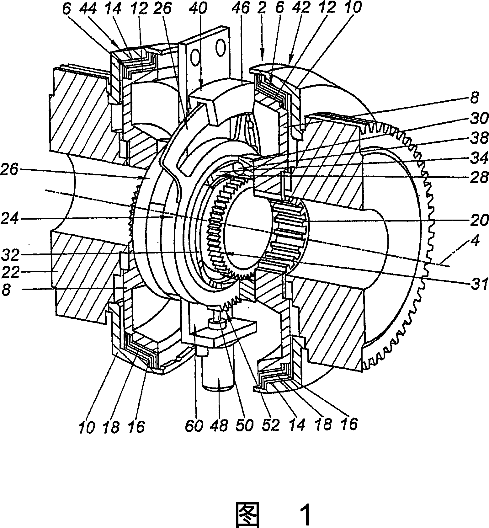
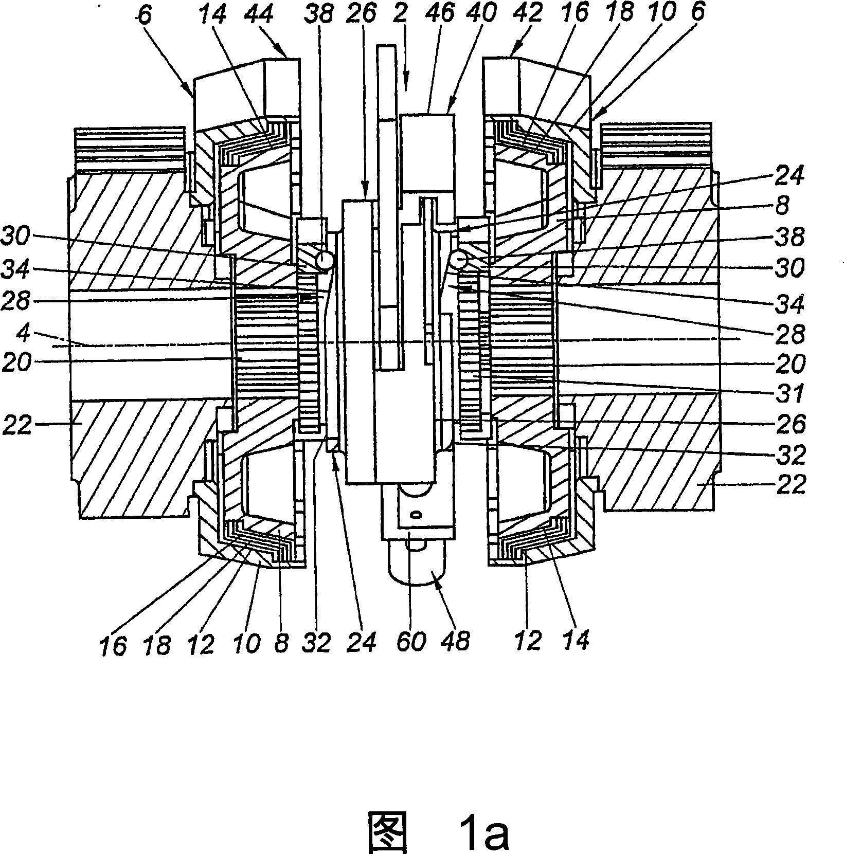
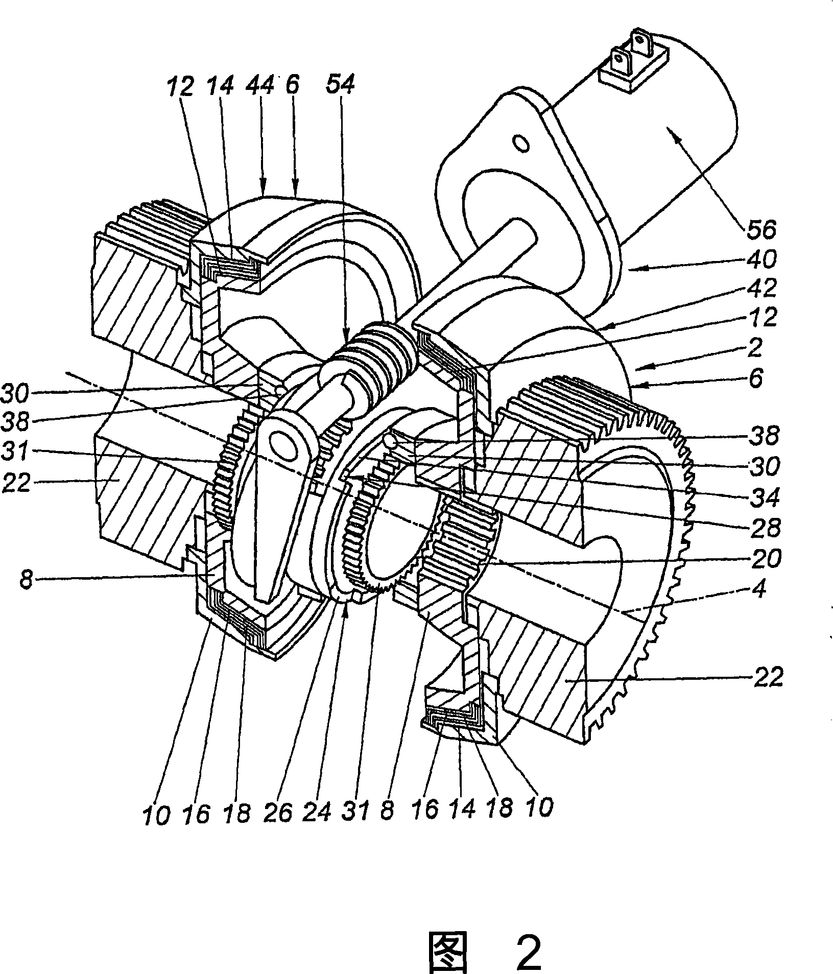
[0026] The clutch 2 serves for the rotational connection of at least two drive parts rotating about an axis of rotation 4 . The clutch 2 comprises at least one clutch device 6 with a first clutch body 8 and a second clutch body 10 such that the first clutch body 8 forms at least one first clutch surface 12 and the second clutch body 10 forms at least one second clutch body 10. clutch surface 14 . In various embodiments, the clutch device 6 is arranged as a multi-cone disc clutch such that the mutually facing first and second clutch surfaces 12, 14 have a conical shape. The disc bodies 16, 18 are arranged between the first and second clutch surfaces 12, 14, alternately with each first disc body 16 being rotatably connected to the first clutch body 8 and the second disc body 18 being connected to the second The clutch body 10 is maintained in an axially movable manner. Multi-c...


PUM


Abstract

The invention relates to a clutch ( 2 ), especially for motor vehicles, for the torque connection of at least two drive parts which are rotatable about a rotational axis ( 4 ), comprising at least one clutch device ( 6 ) with a first clutch body ( 8 ) with at least one first clutch surface ( 12 ) and a second clutch body ( 10 ) with at least one second clutch surface ( 14 ), with said first and second clutch body ( 8, 10 ) being coaxially displaceable relative to each other by means of an actuating means ( 24 ) and said first and second clutch surface ( 12, 14 ) being mutually connectable in a non-positive way in at least one clutch engagement position, with the actuating means ( 24 ) comprising at least one ring gear ( 26 ) which comprises a ramp mechanism ( 28 ) and is twistable about the rotational axis ( 4 ) by an actuator ( 40 ), which mechanism, in the clutch engagement position, presses the first clutch body ( 8 ) against the second clutch body ( 10 ). The actuator ( 40 ) acts substantially in a tangential direction on the ring gear ( 26 ) via a linear motor ( 46 ), a worm gear ( 54 ) or a gearshift rod ( 58 ).

Description

technical field [0001] The invention relates to a clutch, in particular a clutch for a motor vehicle, for torque-coupling at least two drive parts rotating about a rotational axis, the clutch comprising at least one clutch device having at least one first A first clutch body of a clutch surface and a second clutch body with at least one second clutch surface, said first and second clutch bodies are coaxially displaced relative to each other by means of an actuating device, said first The first and second clutch surfaces are connectable to each other in at least one clutch engaged position in a non-positive way, the actuating means comprising at least one ring gear comprising a ramp mechanism and actuated by a The mechanism is twisted about the axis of rotation, the mechanism in the clutch engaged position presses the first clutch body against the second clutch body. Background technique [0002] A friction clutch is known from US Patent No. 6,676,555 B2, which can be contro...

Claims


Application Information

Patent Timeline
IPC IPC(8): F16D13/28F16D23/12F16D27/00
CPCF16D27/004F16D13/28F16D23/12F16D28/00
Inventor S·哈戈瑞伍斯F-P·杰格尔B·普费弗
Owner INT INNOVATIONS
Learn More