flywheel assembly

A technology of flywheels and components, applied in flywheels, electric components, vehicle components, etc., can solve the problems of increasing the cost of manufacturing components, weakening plates, and deformation of flywheel quality, and achieve the effect of reducing aerodynamic wind resistance and reducing stress concentration

Active Publication Date: 2017-12-05
CITY UNIV
View PDF4 Cites 2 Cited by
  • Summary
  • Abstract
  • Description
  • Claims
  • Application Information

AI Technical Summary

Problems solved by technology

However, if the flywheel mass is rotated at high speed, the stresses caused by the centrifugal force on the flywheel mass of the assembly can cause the flywheel mass to deform, leading to several potential problems
[0005] One such problem is that the flywheel mass disengages from matching flush contact with the rotating axle as the mass deforms away from the axle
[0009] Unfortunately, one drawback associated with this solution is that the manufacturing costs of the flywheel assembly are increased, mainly due to the presence of both the hub 2 and the counterweight 5 in addition to the one or more discs 4
This increases the cost of manufacturing the assembly and prevents manufacturers from making this assembly in parts of the world where such machines are not readily available
Second, drilling holes in the top and bottom plates in order to be able to attach the axial hub inevitably weakens the plates, increasing the risk of failure
Third, the interlocking of the protrusions and recesses that align the plate to the disc creates stress points at each discontinuity that necessarily reduce the maximum feasible rotational speed of the flywheel mass

Method used


Image

  • flywheel assembly
  • flywheel assembly
  • flywheel assembly

Examples


Embodiment Construction

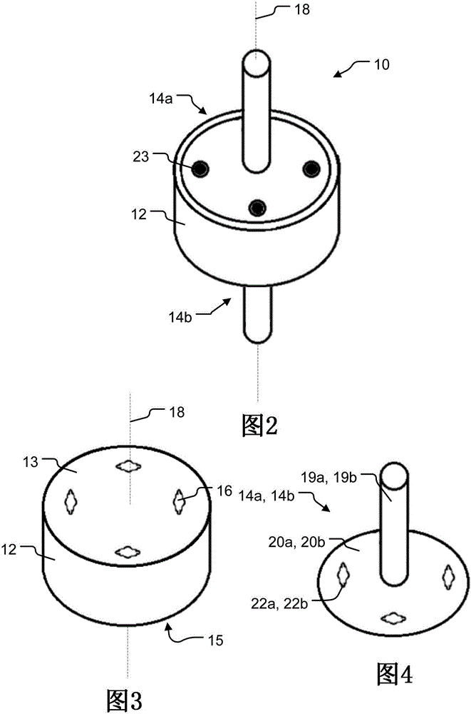
[0045] figure 2 is a schematic illustration of a conceived flywheel assembly 10 comprising a flywheel mass 12 sandwiched between and connected to two flywheel mass supports 14a, 14b.

[0046] see image 3 The flywheel mass 12 comprises a body having one or more through holes 16, each radially offset from an axis of rotation 18 about which the flywheel mass 12 rotates in use.

[0047] Such as Figure 4 As shown in , each flywheel support 14a, 14b comprises a plate 20a, 20b and an axial shaft 19a, 19b defining the aforementioned axis 18 about which the plates 20a, 20b can rotate. The plates 20a, 20b comprise two or more through holes 22a, 22b each radially offset, such holes being offset from the shaft 19a, 19b. The holes 22a, 22b are positioned such that they can be aligned with the holes 16 in the flywheel element 12 when the plates 20a, 20b are against the flywheel mass 12 . In one particular configuration, the apertures 22a, 22b defined by the plates 20a, 20b have a cros...


PUM


Abstract

A flywheel assembly (10) comprising at least one flywheel mass support (14), the or each said support having a shaft (19) extending along an axis of rotation (18), said support in use (14) rotatable about the axis of rotation, the or each said support (14) comprising a plurality of openings (24) each offset from said axis of rotation (18); comprising a plurality of openings (24) each arranged with a flywheel mass (12) with openings (16) aligned with corresponding openings in said support; and a mechanism (23) for connecting said flywheel mass (12) to the support or to each said a support (14) such that in use said mass (12) can rotate with the or each said support (14), said linkage (23) being arranged to extend through the support or aligned openings in each of said supports (14) and said flywheel mass (12), wherein said flywheel mass (12) comprises a plurality of substantially planar flywheels clamped together to form a stack of elements mass elements, each said element comprising a plurality of openings (16) aligned with openings (24) in the or each said support (14) and with adjacent elements in said stack alignment of the openings in said flywheel elements, said flywheel elements are connected together and against each other only by means of connecting means (23) extending through said elements and aligned openings in the or each said support (14) standard while forming the flywheel mass.

Description

technical field [0001] The present invention relates to flywheel assemblies and flywheel masses for use in such assemblies. Background technique [0002] Previously proposed flywheel assemblies comprise a flywheel mass having a bore therethrough along an axis of rotation about which the flywheel mass rotates in use. The axle passes through the hole in the flywheel mass so as to form an interference fit with the flywheel mass. In this configuration, rotating the axle causes the flywheel mass to rotate about the axis of rotation. [0003] A flywheel assembly of the kind described above is used to store energy in the form of kinetic energy. For example, when the car is stopped, the translational kinetic energy of the car can be converted into rotational kinetic energy of the on-board flywheel assembly instead of being dissipated as heat in the car's brakes. The rotational kinetic energy can then be recovered and converted into translational kinetic energy of the vehicle by m...

Claims


Application Information

Patent Timeline
Patent Type & Authority Patents(China)
IPC IPC(8): H02K7/02B60L50/30
CPCY02E60/16F16F15/30H02K7/003B60L50/30Y10T74/2119H02K7/025Y02T10/64Y02T10/70F16F15/315F16F15/3153
Inventor K·R·普伦
Owner CITY UNIV
Why Eureka
Try Eureka