Ship with liquid transport tanks provided with deformation absorbers

a technology of liquid transport tanks and absorbers, which is applied in the direction of waterborne vessels, special purpose vessels, floating buildings, etc., can solve the problems of undesirable mixing of stored products, cracks in the tank walls, and formation of cracks, and achieves simple construction and little to no maintenance

Active Publication Date: 2011-12-27
ORKA BV
View PDF6 Cites 2 Cited by
  • Summary
  • Abstract
  • Description
  • Claims
  • Application Information

AI Technical Summary

Benefits of technology

[0008]The object of the present invention is to provide a ship with one or more liquid transport tanks placed in a ship's hull, in which the abovementioned disadvantages are at least partially overcome, or to provide a usable alternative. In particular, the object of the invention is to provide a great saving on m

Problems solved by technology

The disadvantage here is that cracks can occur in the tank walls through deformations of the ship in heavy seas and through temperature differences.
The abovementioned deformations cause high stress concentrations in the tanks, particularly on the corner points, which can result in the formation of cracks.
If this happens, an opening can develop between two adjacent tanks, with the result that undesirable mixing of the stored products can occur.
However, the tanks are difficult to clean.
This means that a relatively large quantity of flushing water is needed for cleaning the tanks, which is expensive and undesirable from an environmental point of view because the flushing water sometimes has to be di

Method used


Image

  • Ship with liquid transport tanks provided with deformation absorbers
  • Ship with liquid transport tanks provided with deformation absorbers
  • Ship with liquid transport tanks provided with deformation absorbers

Examples


Embodiment Construction

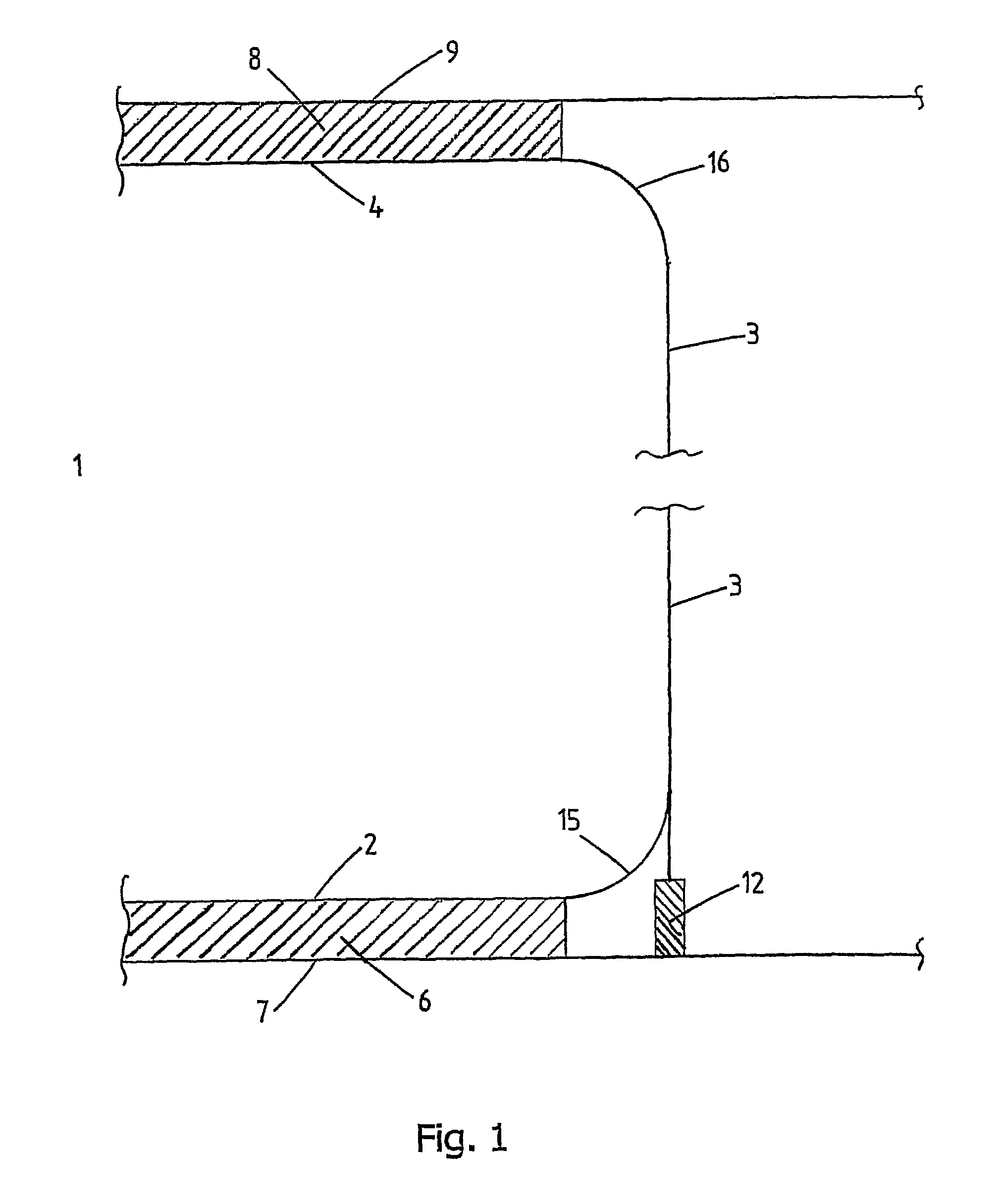
[0040]In FIG. 1 the transport tank is indicated in its entirety by the reference numeral 1. The transport tank 1 consists of a tank bottom 2, a cylindrical tank circumferential wall 3 and a tank roof 4. The tank bottom 2 is of a flat design and, with the interposition of an insulating layer 6, is connected to a lower deck 7 of a hull of a ship not shown in any greater detail. The tank roof 4 is connected to an upper deck 9 of the ship's hull, with the interposition of an insulating layer 8. The tank circumferential wall 3 is partially supported towards the bottom by deformable support means 12. The support means 12 engage upon the bottom part of the tank circumferential wall 3. Deformation absorbers 15, 16 are accommodated in the tank wall. The deformation absorbers 15, 16 are formed here as sections which are quadrantal-shaped (shaped like a quarter circle) in cross section and extend between the tank bottom 2 or the tank roof 4 and the tank circumferential wall 3 respectively. The...


PUM


Abstract

A ship (20) with one or more liquid transport tanks (21) arranged in an upright position in a ship's hull, said transport tanks having an axial direction and a circumferential direction, and each transport tank comprising a tank bottom (22), a tank circumferential wall (25) and a tank roof (23), the tank bottom being supported on or forming part of a lower deck of the ship's hull. The tank circumferential wall is suspended by its lower and upper ends by means of deformable deformation absorbers (26) between the lower deck and an upper deck (24) of the ship's hull, which deformation absorbers are designed so as to absorb deformations between the ship's hull and the tank circumferential wall at least in the abovementioned axial direction, at least the lower deformation absorber extending in the circumferential direction around substantially the entire circumference of the tank circumferential wall, and at least the lower deformation absorber forming part of the tank wall and being accommodated at the position of the transition between the tank circumferential wall and the tank bottom so as to form a continuous sealing connection between them.

Description

CROSS-REFERENCE TO RELATED APPLICATIONS[0001]This application is the National Stage of International Application No. PCT / NL2006 / 000171, filed Apr. 3, 2006, which claims the benefit of Netherlands Application No. NL 1028679, filed Apr. 1, 2005, the contents of which are incorporated by reference herein.FIELD OF THE INVENTION[0002]The invention relates to a ship with one or more liquid transport tanks which are provided in a ship's hull for transporting liquid media.BACKGROUND OF THE INVENTION[0003]The current mode of transporting liquid media, such as chemicals, oil and agricultural products, is mainly in tankers which are equipped with rectangular cargo tanks that are integral with the ship, so-called parcel tankers. The cargo tanks are part of the ship's structure, in which the tank walls are formed by the ship's hull, profiled cross bulkheads and longitudinal bulkheads placed therein, and the ship's deck.[0004]The disadvantage here is that cracks can occur in the tank walls throug...

Claims


Application Information

Patent Timeline
IPC IPC(8): B63B25/08
CPCB63B25/12B63B25/02
Inventor KOOLE, JACOBVAN POPPELEN, MARTIJN PIETER
Owner ORKA BV
Why Eureka
Try Eureka