

Method for manufacturing integral vacuum chamber of vacuum refining device
A vacuum refining and manufacturing method technology, applied in the field of integral vacuum tank chamber manufacturing, can solve the problems of low processing efficiency and high processing cost, achieve high processing efficiency, reduce processing difficulty, and improve processing efficiency
- Summary
- Abstract
- Description
- Claims
- Application Information
AI Technical Summary
Problems solved by technology
Method used
Image

Examples
Embodiment Construction
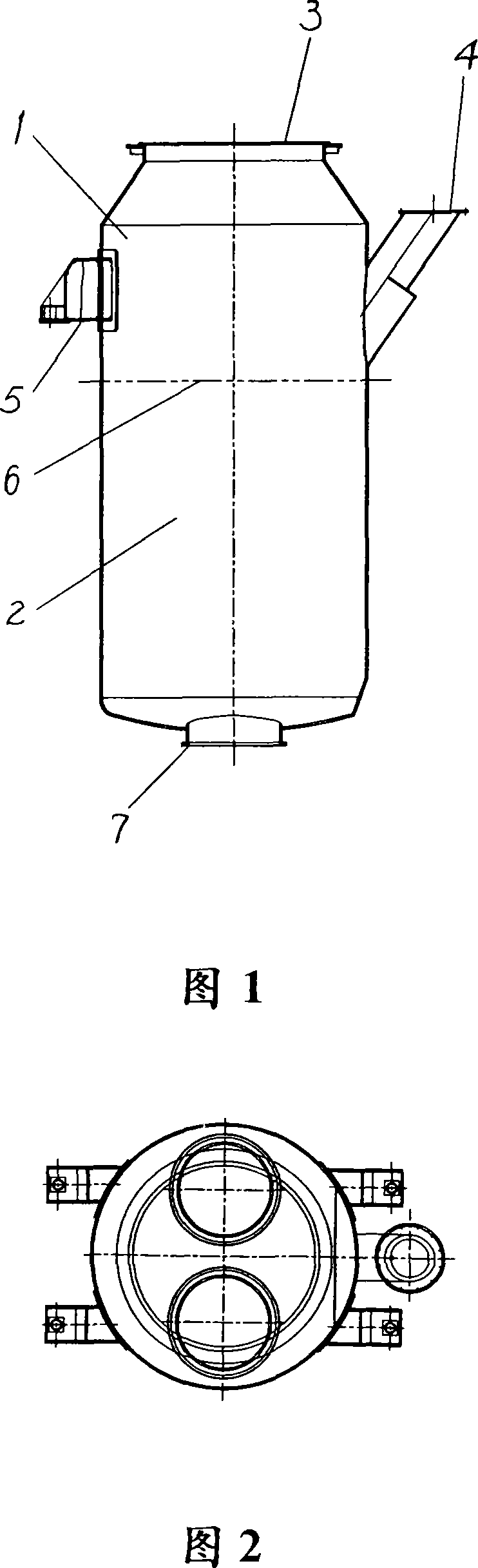
[0020] Referring to the integrated vacuum chamber of the vacuum refining device of Fig. 1 and Fig. 2, the integral vacuum chamber of the vacuum refining device is manufactured according to the manufacturing method of the present invention, and processed according to the following steps, with 300 tons of RH vacuum refining Device example:
[0021] 1. Divide the integral vacuum tank chamber into two sections for manufacture. The height from the upper flange 3 to the bottom is in the range of 3000-3400mm as the upper section 1, and the height of the rest is taken as the lower section 2. The joint of the two sections is fully melted. Butt welded joints 6 and 100% ultrasonic or radiographically inspected. The height of the upper section 1 of the integral vacuum chamber from the upper flange 3 to the bottom is in the range of 3000-3400 mm, and the upper section 1 includes the upper flange surface and sealing groove, the feeding port 4 flange and the vacuum chamber support 5 .
[0...
PUM
 Abstract
Description
Claims
Application Information