
Vehicle plate surface galling defect inducing device

An automobile sheet and defect technology, which is applied in the field of automobile sheet surface roughening defect inducing devices

Inactive Publication Date: 2007-12-05
BAOSHAN IRON & STEEL CO LTD
View PDF0 Cites 8 Cited by
  • Summary
  • Abstract
  • Description
  • Claims
  • Application Information

AI Technical Summary

Problems solved by technology

This paper reveals that U-shaped bending deformation is used to study the wear resistance of automobile sheet stamping dies. They all realized the simulation of wear in the experiment, but they also have obvious limitations, mainly in the bending of U-shaped molds. Abrasion and sheet scratches only occur on the straight-edge part of the bending molding, while for automotive panels with various geometric shapes, the forming mode is tensile deformation, that is, except for the bending deformation at the larger straight-edge part, other parts are uniform It is tensile deformation, which belongs to sheet metal compression molding, and the napping defect at the corner of the mold is more common than the napping at the straight edge, so the bending deformation of U-shaped parts is used to simulate the wear of the mold (or the anti-picking of the sheet metal) properties) have great limitations in the study of the napping characteristics of automobile panels, and cannot provide corresponding technical support for the study of the influence of various factors on the napping behavior and the establishment of scientific evaluation of napping defects.

Method used


Image

  • Vehicle plate surface galling defect inducing device
  • Vehicle plate surface galling defect inducing device
  • Vehicle plate surface galling defect inducing device

Examples


Embodiment Construction

[0020] In order to better understand the above technical solutions of the present invention, a further detailed description will be given below in conjunction with the drawings and embodiments.

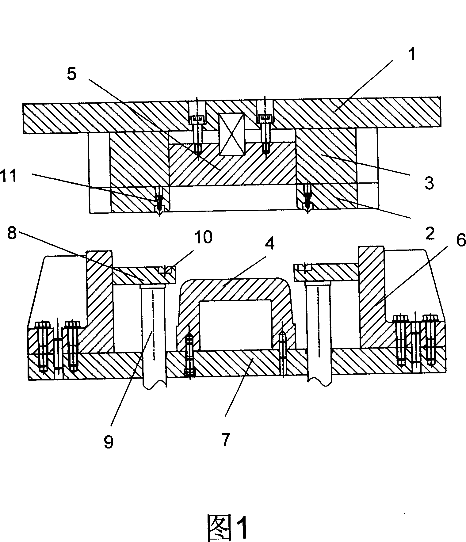
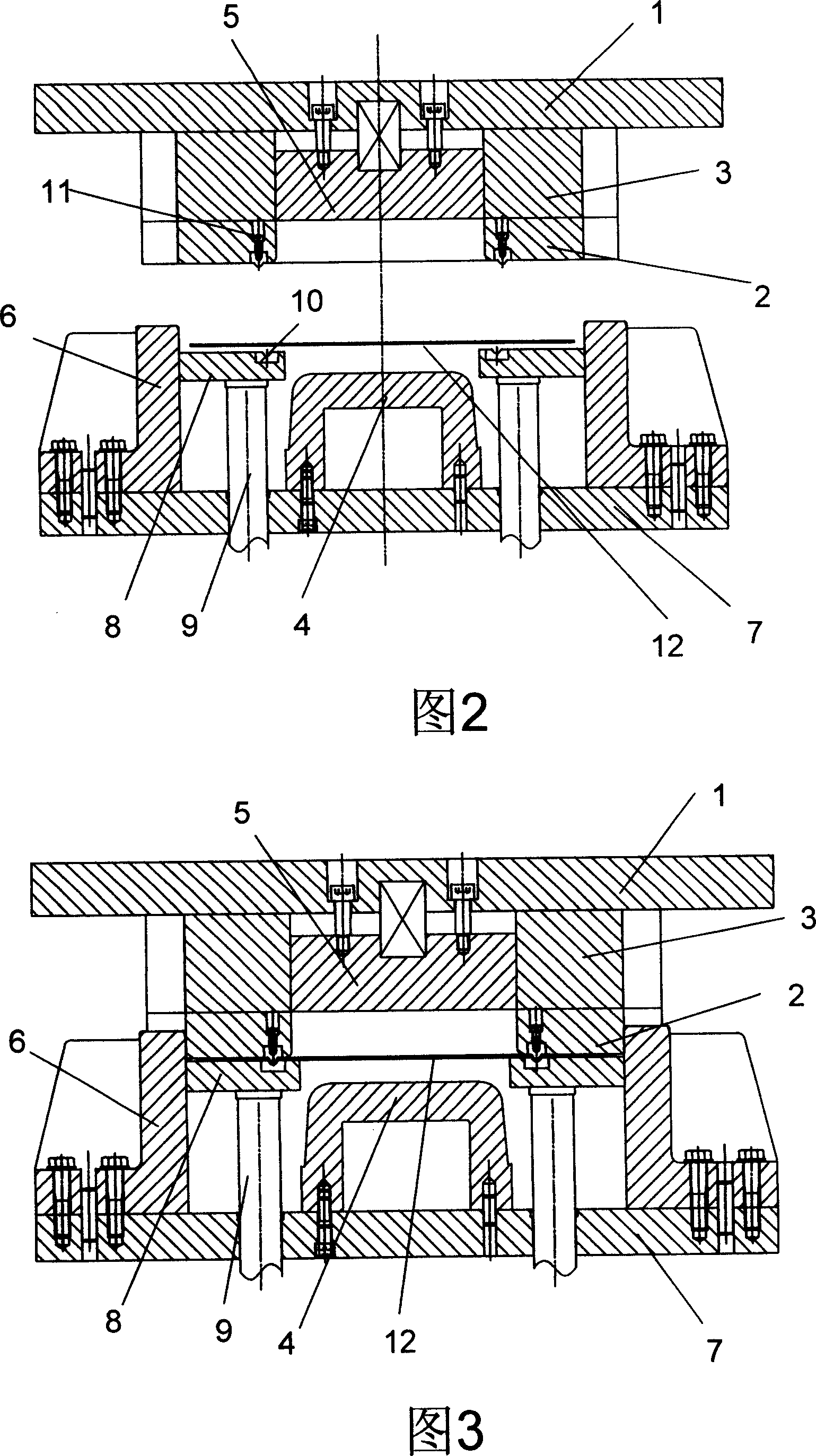
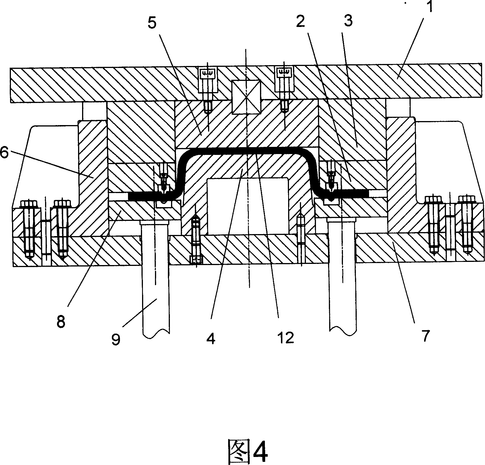
[0021] As shown in Figure 1, the napping induction device of the present invention includes a press, a die part and a punch part, specifically including an upper base plate 1, a die 2, a die pad 3, a punch 4, and a punch pad 5 , the back guide block 6, the lower bottom plate 7, the blank holder 8, the ejector pin 9, the blank holder draw bead concave rib 10, the die draw bead convex rib 11.

[0022] The upper base plate 1 is connected with a component in the press machine (not shown in the figure), and the upper base plate 1 is driven by the press machine to move up and down. Die spacer 3 is fixed on the upper base plate 1 by hexagon socket head cap screws and internal thread cylindrical pins, convex die spacer 5 is fixed on the upper base plate 1 by unloading screws, and die 2 is inl...


PUM

PropertyMeasurementUnit
Surface roughnessaaaaaaaaaa

Abstract

The invention discloses a kind of car board surface galling flaw induction equipment which includes the cavity die section and the male die section and the cavity section includes a top bottom board, a cavity, a cavity bearer supporting bracket and the male die section includes the down bottom board, male die, back guide block, pressure side board, active top bar, and the male die fixes on the down bottom board and corresponds with the cavity backup plate of the cavity die section and the active top bar lays on the down bottom board and lays at the two sides of the sale die and the back guide block fixes on the down bottom board and lays at the two sides of the top bar and the pressure side board lays on the top bar. When the nickelclad lays on the induction equipment on the pressure board and the cavity die moves downstream driving by the pressure machine and at the time of the cavity tie contacting the nickelclad the pressure side board moves downstream with the cavity die and forms the bonding knob on the surface of cavity die and pressure side board surface and during the process of press the bonding knob may fish tail the surface of the nickelclad generating the galling flaw and with the increasing of pressure times the degree of the galling becomes more and more seriously and it provides the technology support for the evaluation system of the galling flaw.

Description

technical field [0001] The invention relates to the detection of finished steel plate products in metallurgical smelting, and more specifically refers to an induction device for roughening defects on the surface of automobile plates, which can form roughening defects on the surface of automobile plates. Background technique [0002] In stamping forming of cold-rolled steel sheets, especially sheet stretching, when the sheet is in sliding motion, due to the forced contact between the sheet and the working surface of the die, adhesive wear may occur, and the formed part will be severely damaged , that is, the surface damage of the stamping parts - the phenomenon of napping. In production, by reducing napping defects, the surface quality and yield of products can be improved. Therefore, it is very important for automakers and automotive sheet suppliers to study the phenomenon of picking and the measures to prevent it. During the stamping and forming process of cold-rolled ste...

Claims


Application Information

Patent Timeline
IPC IPC(8): G01N1/28
Inventor 陈新平蒋浩民
Owner BAOSHAN IRON & STEEL CO LTD
Learn More