
Method and device for the inspection of a rolled strip

An inspection method and inspection device technology, applied in the field of rolling metal strips, capable of solving problems such as scar formation

Active Publication Date: 2007-12-05
PRIMETALS TECH AUSTRIA GMBH
View PDF1 Cites 18 Cited by
  • Summary
  • Abstract
  • Description
  • Claims
  • Application Information

AI Technical Summary

Problems solved by technology

Such a technique can be used on small strip samples, the inversion being done by hand, but it is often desirable to inspect over a larger length, say 10m to 15m in length, in order to detect defects that periodically occur during rolling, and these defects may have different causes
For this purpose, a sample of the desired length can be taken from the strip, but if this sample is placed on a table for honing the upper surface, the lower surface runs the risk of scarring from contact with the table, and after turning over , it is difficult to know whether these possible found defects come from the rolling or from the honing operation itself, since these defects are of the artéfact type

Method used


Image

  • Method and device for the inspection of a rolled strip
  • Method and device for the inspection of a rolled strip
  • Method and device for the inspection of a rolled strip

Examples


Embodiment Construction

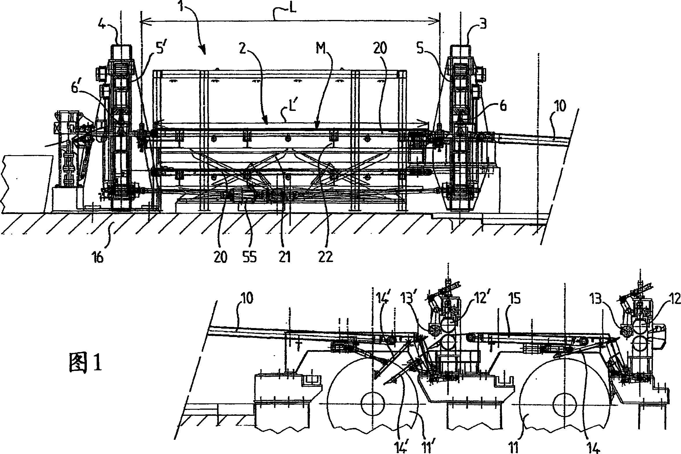
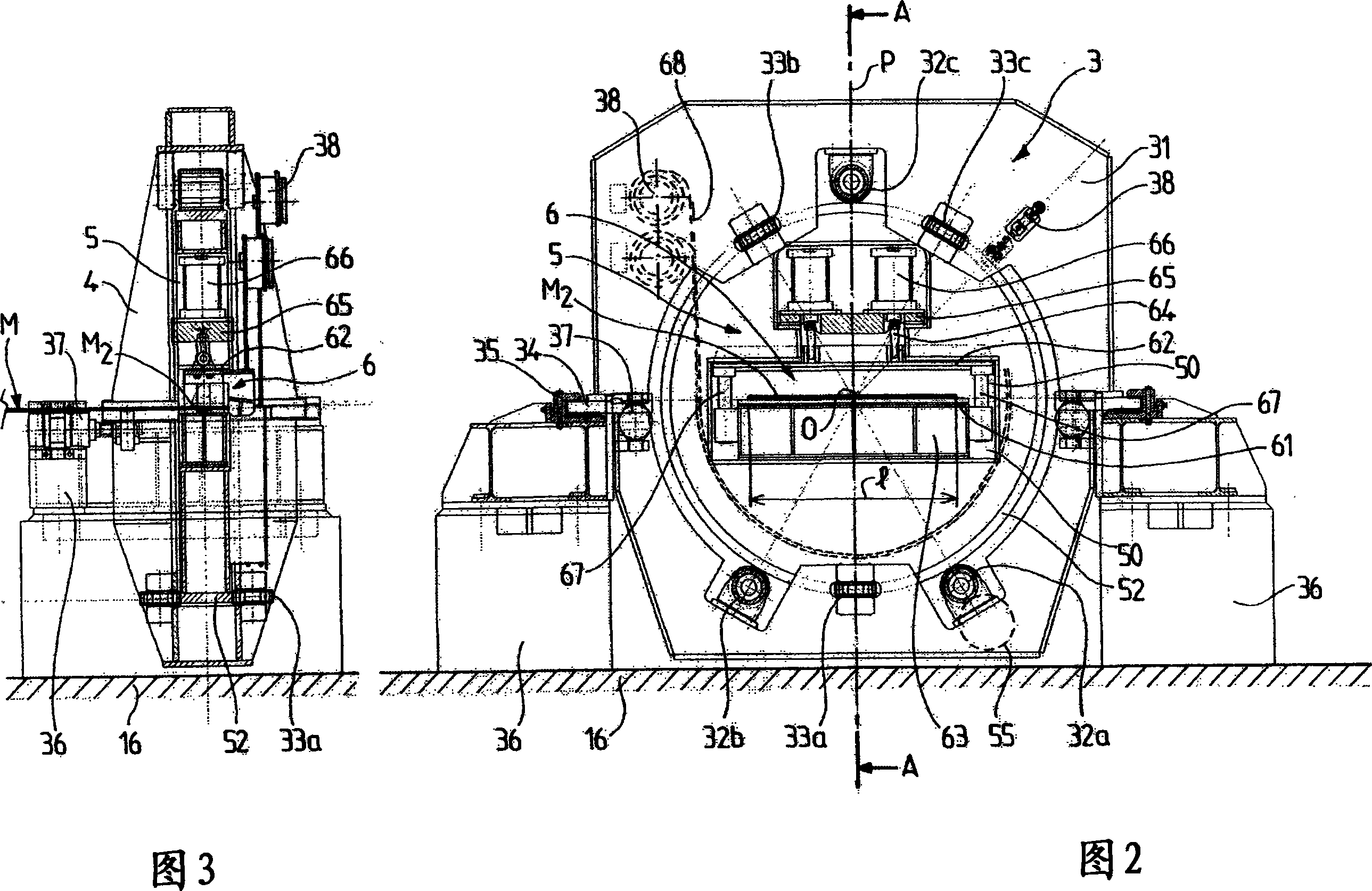
[0036] [36] FIG. 1 shows in elevation the whole of an inspection device 1 located downstream of a continuous strip processing facility such as a rolling facility. The device is not shown in the figures, only the outlet of the device is shown, which comprises, as usual, two coilers 11, 11' which operate alternately to enable continuous travel of the rolled strip.

[0037] [37] Each winder 11, 11' is equipped with a pair of pressure rollers 12, 12', a vertically movable shunt roller (rouleau aiguilleur) 13, 13' and a guide device 14, 14'. At the end of the winding of a strip, for example on the first winder 11 , a clipper located upstream and not shown in the figure can cut the tail of the first strip. The strip finishes its winding on the winder 11, and the head of the next part of the strip is led by an intermediate station 15 to the second winder 11', and through the diverting roller 13' and the guide 14' to the second winder 11'. The chuck of the second winder 11' moves. T...


PUM


Abstract

The invention relates to a method and device for the inspection of a rolled strip, wherein a strip sample (M) is inspected on a first surface thereof and then turned over in order to inspect the second surface thereof. According to the invention, by displacement parallel to the longitudinal axis thereof, the strip sample (M) is placed is placed between two spaced squeezing devices (6, 6') (7, 7') which are respectively tightened on each transversal extremity (M1, M2) of the sample (M); the two squeezing devices (6, 6') (7, 7') are longitudinally separated from each other in order to place the sample in a state of tension for the visual inspection of a first surface, then the sample is turned over by simultaneous rotation of the two squeezing devices (6, 6') (7, 7') about the longitudinal axis O, with maintenance of the applied tension, in order to carry out inspection of the second surface, said tension being sufficient in order to carry out inspection without the need for placement on a table. The invention makes it possible to inspect a strip as it exits from a continuous rolling line.

Description

technical field [0001] [01] The present invention relates to a method and apparatus for inspecting strip products, in particular rolled metal strip. Background technique [0002] [02] During the rolling of a strip-shaped product such as a plate, a marquage may develop on one or the other surface of the product, for example when it comes into contact with a roll, and this marquage may be removed during the rolling process Repeats periodically, and thus continues along the coil after the tape has been wound. It is therefore necessary to regularly inspect the plate coming out of the rolling mill in order to check for possible geometrical defects in the product. For this purpose, it is proposed, for example, to use a device of the unwinder / winder type comprising an unwinder / winder connected to an inspection table. The coils to be inspected thus come out of a conventional conveyor in order to be placed on the unwinder which unwinds a length of strip on an inspection table for ...

Claims


Application Information

Patent Timeline
IPC IPC(8): B21C51/00B24B33/055G01N19/08G01M99/00
CPCB21C51/00B21B38/00B21B39/30B21B39/32G01N1/04G01N3/08G01N19/08G01N2203/0278G01N2203/0282G01N2203/04B24B33/055
Inventor B·罗西尼厄
Owner PRIMETALS TECH AUSTRIA GMBH
Learn More