Elevator controller
A technology of an elevator control device and a speed control device, which is applied in the field of elevator control devices, can solve problems such as slow speed, increased burden on driving equipment, and inability to fully utilize the capacity of driving equipment, and achieves the effect of avoiding voltage saturation
- Summary
- Abstract
- Description
- Claims
- Application Information
AI Technical Summary
Problems solved by technology
Method used
Image
Examples
Embodiment approach 1
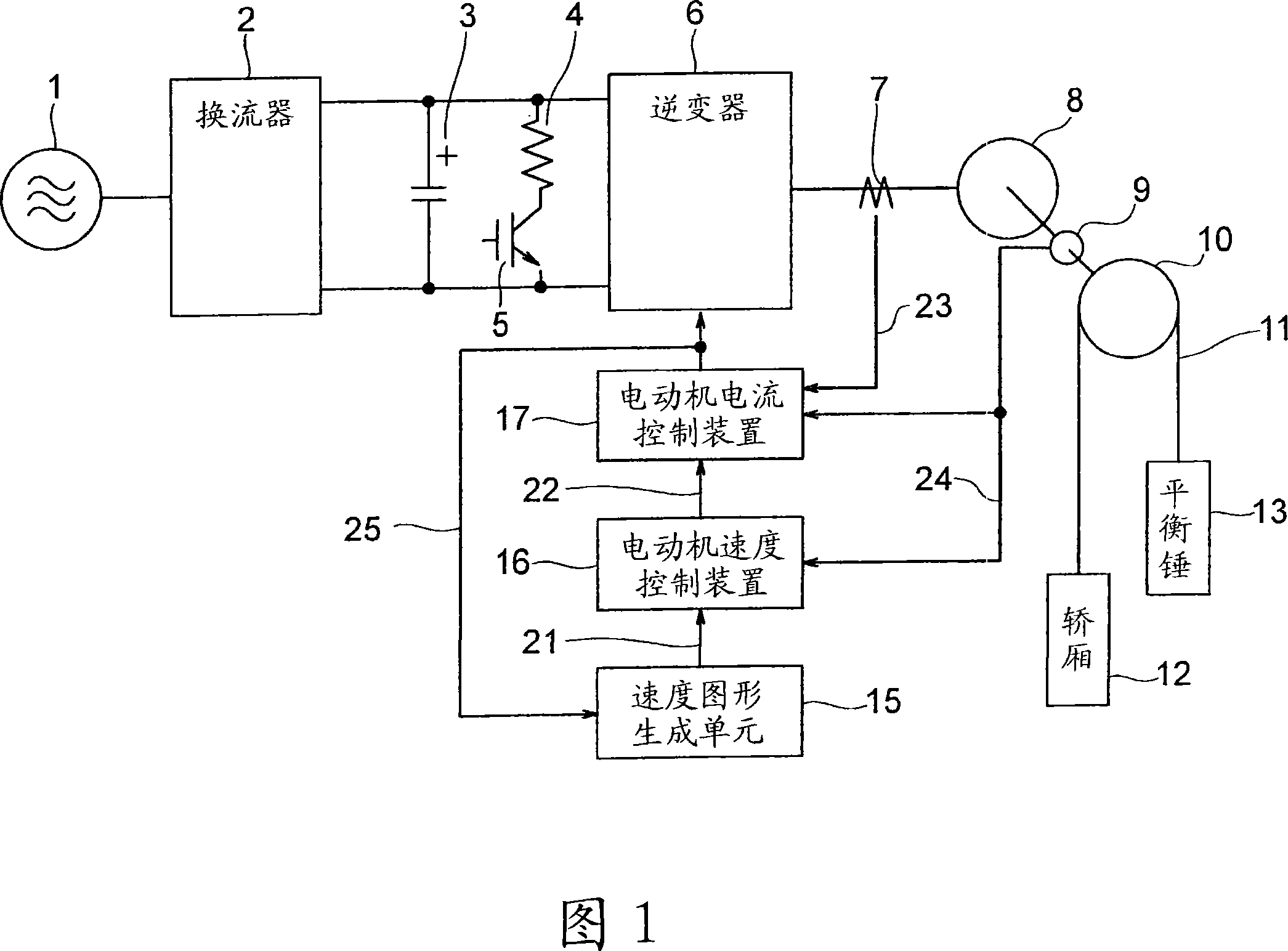
[0022] Fig. 1 is a block diagram showing the configuration of an elevator control device according to Embodiment 1 of the present invention. The elevator control device shown in FIG. 1 has: an inverter 2, which converts the alternating current from the alternating current power source 1 into direct current; a smoothing capacitor 3, which smoothes the direct current output from the inverter 2; A regenerative resistor 4 and a regenerative switch 5 connected in parallel with the smoothing capacitor 3 constitute; and an inverter 6 that converts the DC output of the converter 2 smoothed by the smoothing capacitor 3 into an AC to provide to the motor 8; the elevator control The device drives a motor 8 to raise and lower a car 12 connected to the other end of a rope 11 to which a counterweight 13 is connected via a pulley 10 at one end.
[0023] And, the elevator control device shown in FIG. 1 has: a current detector 7, which detects the current supplied to the motor 8 from the inver...
Embodiment approach 2
[0042] Fig. 4 is a block diagram showing the configuration of an elevator control device according to Embodiment 2 of the present invention. In the configuration of Embodiment 2 shown in FIG. 4 , the same parts as those of Embodiment 1 shown in FIG. 1 are denoted by the same symbols, and description thereof will be omitted. In this FIG. 4 , for the structure of Embodiment 1 shown in FIG. 1 , it further includes: a bus voltage measurement unit 26 that measures the DC voltage smoothed by the smoothing capacitor 3 ; and a voltage calculation unit 27 that detects The output signal of the unit 26 and the duty ratio calculate the voltage applied to the motor 8 ; the speed pattern generation unit 15 changes the speed pattern of the motor 8 based on the output of the voltage calculation unit 27 .
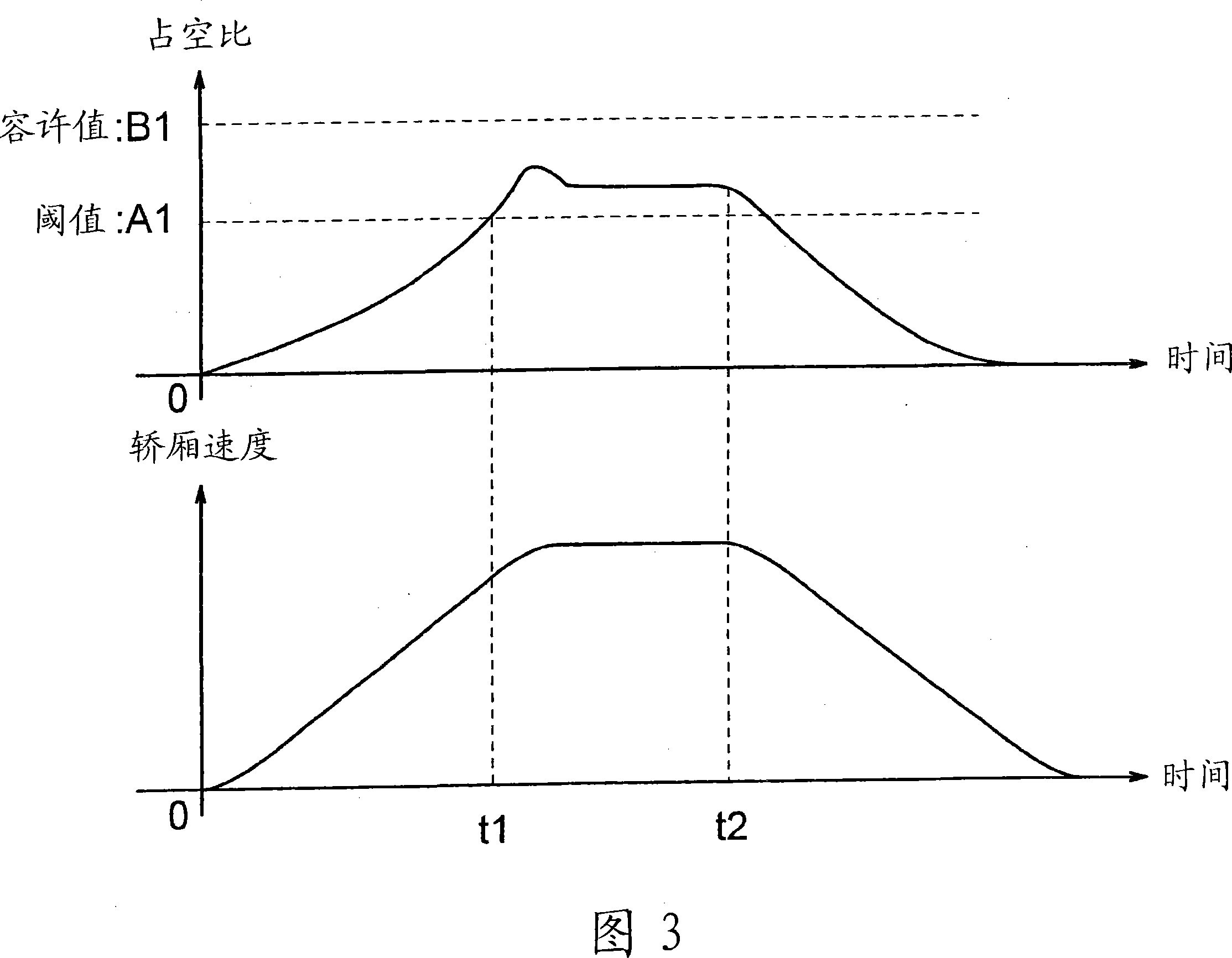
[0043] That is, by using the speed pattern generation unit 15 to compare the output of the voltage calculation unit 27 with the threshold value shown in FIG. , the voltage applied to the m...
Embodiment approach 3
[0046] Fig. 5 is a block diagram showing the configuration of an elevator control device according to Embodiment 3 of the present invention. In the configuration of Embodiment 3 shown in FIG. 5 , the same parts as those of Embodiment 1 shown in FIG. 1 are denoted by the same symbols, and description thereof will be omitted. In this FIG. 5 , for the structure of Embodiment 1 shown in FIG. 1 , a target floor setting unit 28 is provided in the preceding stage of the speed pattern generating unit 15 , and the target floor setting unit 28 generates In response to an instruction to move to the target layer, the speed pattern generation unit 15 changes the acceleration magnitude of the speed pattern generated based on the moving distance to the target layer set by the target layer setting unit 28 .
[0047] That is, the target layer setting unit 28 performs the following actions according to its moving distance: as shown in FIG. For long-distance movement other than this, select low...
PUM
 Abstract
Description
Claims
Application Information
 - R&D
- Intellectual Property
- Life Sciences
- Materials
- Tech Scout
- Unparalleled Data Quality
- Higher Quality Content
- 60% Fewer Hallucinations
Browse by: Latest US Patents, China's latest patents, Technical Efficacy Thesaurus, Application Domain, Technology Topic, Popular Technical Reports.
© 2025 PatSnap. All rights reserved.Legal|Privacy policy|Modern Slavery Act Transparency Statement|Sitemap|About US| Contact US: help@patsnap.com


