Elevator control device
An elevator control device and voltage technology, which is applied in the field of elevator control devices, can solve the problems of increased burden on driving equipment, slow speed, and inability to fully utilize the ability of driving equipment, etc., to improve precision, avoid voltage saturation, and stabilize elevator drive control at high speed Effect
- Summary
- Abstract
- Description
- Claims
- Application Information
AI Technical Summary
Problems solved by technology
Method used
Image
Examples
Embodiment approach 1
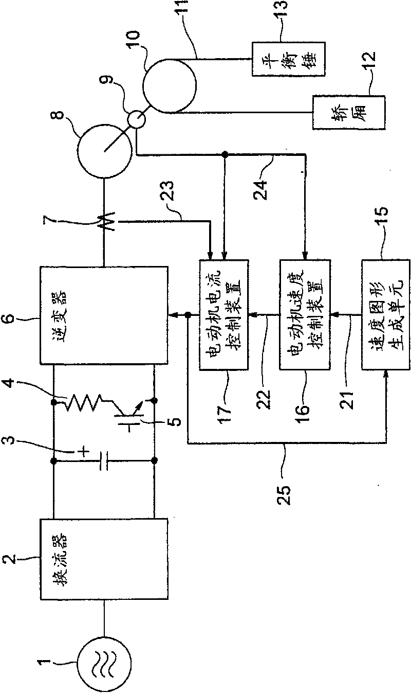
[0020] figure 1 It is a block diagram showing the configuration of the elevator control device according to Embodiment 1 of the present invention. figure 1 The elevator control device shown has: an inverter 2, which converts the alternating current from the alternating current power source 1 into direct current; a smoothing capacitor 3, which smoothes the direct current output from the inverter 2; The capacitor 3 is composed of a regenerative resistor 4 and a regenerative switch 5 connected in parallel; and an inverter 6 that converts the DC output of the converter 2 smoothed by the smoothing capacitor 3 into an AC to provide to the motor 8; the elevator control device drives An electric motor 8 lifts and lowers a car 12 connected to the other end of a rope 11 to which a counterweight 13 is connected via a pulley 10 at one end.
[0021] and, figure 1 The elevator control device shown has: a current detector 7, which detects the current supplied from the inverter 6 to the mot...
Embodiment approach 2
[0040] Figure 4 It is a block diagram showing the configuration of an elevator control device according to Embodiment 2 of the present invention. exist Figure 4 In the structure of Embodiment 2 shown, with figure 1 The parts that are the same as those in Embodiment 1 shown are given the same symbols, and descriptions thereof are omitted. in the Figure 4 in, for figure 1 The structure of Embodiment 1 shown further includes: a bus voltage detection unit 26, which measures the DC voltage smoothed by the smoothing capacitor 3; The voltage applied to the motor 8 is calculated; the speed pattern generation unit 15 changes the speed pattern of the motor 8 based on the output of the voltage calculation unit 27 .
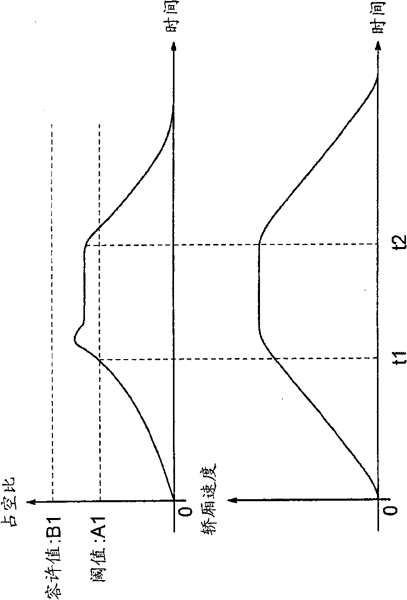
[0041] That is, the output of the voltage operation unit 27 is combined with the speed pattern generation unit 15 image 3 Compared with the threshold values shown, the same effect as that of Embodiment 1 is obtained. Even when the bus voltage fluctuates due to th...
Embodiment approach 3
[0044] Figure 5 It is a block diagram showing the configuration of an elevator control device according to Embodiment 3 of the present invention. exist Figure 5 In the structure of Embodiment 3 shown, with figure 1 The parts that are the same as those in Embodiment 1 shown are given the same symbols, and descriptions thereof are omitted. in the Figure 5 in, for figure 1 In the structure of Embodiment 1 shown, a target floor setting unit 28 is also provided in the preceding stage of the speed pattern generating unit 15, and the target floor setting unit 28 generates an instruction to move the elevator from the current floor to the target floor. The generating unit 15 changes the acceleration magnitude of the velocity pattern generated based on the moving distance to the target layer set by the target layer setting unit 28 .
[0045] That is, the target layer setting unit 28 performs the following actions according to its moving distance: Figure 6 As shown, for example...
PUM
 Abstract
Description
Claims
Application Information
 - R&D
- Intellectual Property
- Life Sciences
- Materials
- Tech Scout
- Unparalleled Data Quality
- Higher Quality Content
- 60% Fewer Hallucinations
Browse by: Latest US Patents, China's latest patents, Technical Efficacy Thesaurus, Application Domain, Technology Topic, Popular Technical Reports.
© 2025 PatSnap. All rights reserved.Legal|Privacy policy|Modern Slavery Act Transparency Statement|Sitemap|About US| Contact US: help@patsnap.com


