Tool for machining a hole

A hole processing and tool technology, applied in the direction of manufacturing tools, metal processing equipment, hole reaming devices, etc., can solve problems such as time and labor, achieve good dimensional accuracy and prevent vibration.

Inactive Publication Date: 2007-12-12
MITSUBISHI MATERIALS CORP
View PDF1 Cites 12 Cited by
  • Summary
  • Abstract
  • Description
  • Claims
  • Application Information

AI Technical Summary

Problems solved by technology

Therefore, much time and labor are required to adjust the position of the insert 6, and the position adjustment of the insert 6 cannot be easily and accurately performed.

Method used


Image

  • Tool for machining a hole
  • Tool for machining a hole
  • Tool for machining a hole

Examples


Embodiment Construction

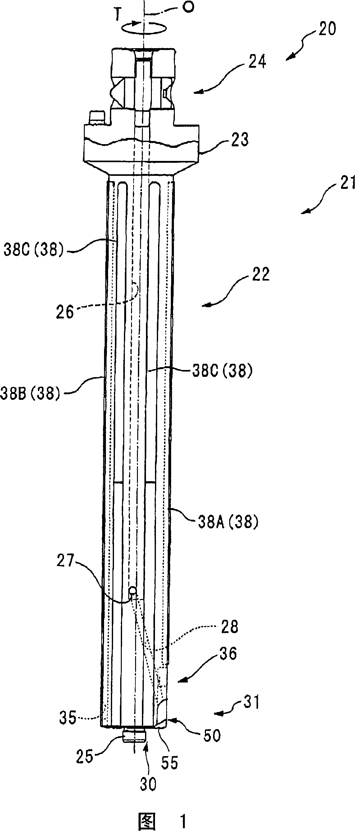
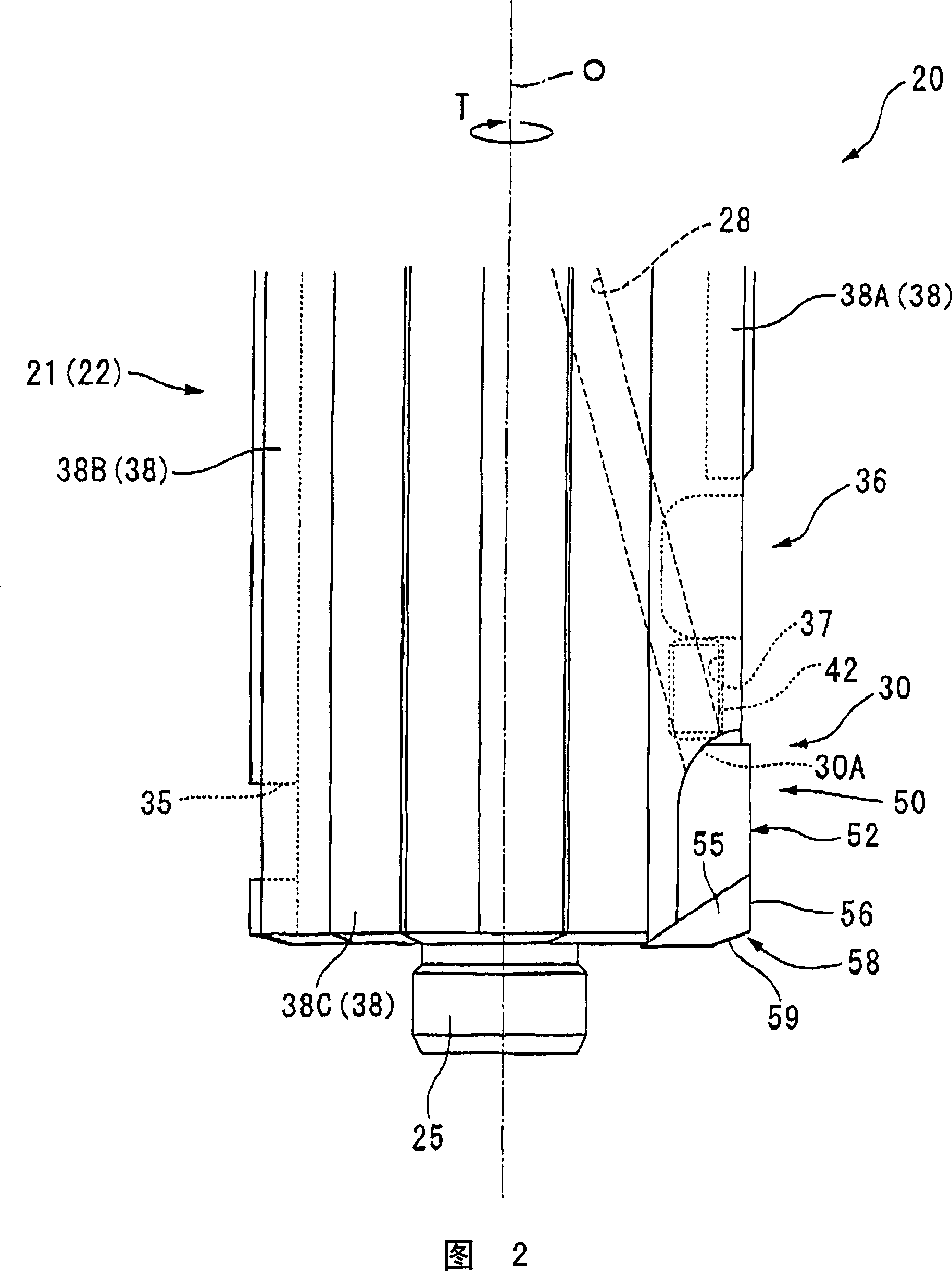
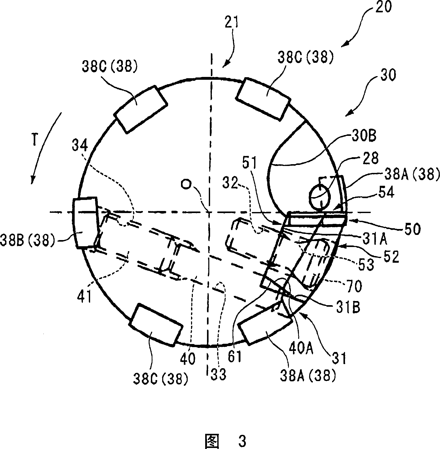
[0056] Next, a drilling tool as a first embodiment of the present invention will be described with reference to the drawings. FIG. 1 to FIG. 3 show a reamer as a drilling tool according to an embodiment of the present invention.

[0057] The reamer 20 according to this embodiment has a multi-stage cylindrical tool body 21 centered on the axis O. The front end side (lower side in FIG. 1 ) of the tool body 21 is a substantially cylindrical processed portion 22. On the rear end side (upper side in FIG. 1 ) of the tool main body 21, a flange portion 23 having a larger diameter than the processed portion 22 is formed. The reamer 20 is mounted on a mounting portion 24 of a tool holder (not shown) on a spindle end of a machine tool.

[0058] In addition, a guide rod 25 having a smaller diameter than the processed portion 22 is provided on the front end surface of the tool body 21 .

[0059] Furthermore, the tool main body 21 is pierced with a cooling part that is opened on the moun...


PUM


Abstract

A hole machining tool is provided in which movement balance and rigidity of a tool body are enhanced and which can simply and precisely adjust a position of an insert to form a machined hole having a high circularity with high dimensional precision. A recessed portion and an attachment seat are formed in a front end portion of the tool body. A panel-shaped insert is attached to the attachment seat in a state where the thickness direction thereof is matched with the diameter direction of the tool body and a surface of the insert facing the rear side in a tool rotation direction becomes a pressed surface. A peripheral cutting edge is formed at a ridge portion of an inclined surface on the outside in the diameter direction of the tool body, a bevel edge is formed at a ridge portion on the front side of the tool body, and a back taper is attached to the peripheral cutting edge. A pressing member (40) for pressing the pressed surface (61) of the insert (50) to adjust a position of the peripheral cutting edge in the diameter direction of the tool body is disposed on the rear side (31B) of the attachment seat (31) in the tool rotation direction (T).

Description

technical field [0001] The present invention relates to a hole machining tool which is inserted into a bottom hole previously formed in a workpiece to be cut and used for cutting the inner wall surface of the bottom hole. Background technique [0002] As such a drilling tool, there is known a reamer in which a tip portion having a cutting edge is brazed to a front end portion of a long cylindrical tool body that rotates about an axis. Rotate the reamer around the axis and apply feed along the axis, insert it into the bottom hole formed in advance on the material to be cut, and cut the inner wall surface of the bottom hole with the cutting edge formed on the cutting edge to form a predetermined inner diameter processing holes. [0003] In the tool in which the blade edge portion is brazed to the tool body in this way, the radial position adjustment of the cutting blade cannot be performed, and the cutting blade position is determined by the brazing accuracy. Therefore, it i...

Claims


Application Information

Patent Timeline
Patent Type & Authority Applications(China)
IPC IPC(8): B23D77/04
Inventor 泷口正治金星彰远藤邦博
Owner MITSUBISHI MATERIALS CORP
Why Eureka
Try Eureka