
Method for measuring eccentricity quantity

A measurement method and technology of eccentricity, applied in the direction of measuring devices, optical axis determination, optical instrument testing, etc., can solve problems such as difficult circle radius and difficult pinhole image, and achieve high-precision eccentricity measurement and simple eccentricity Measured effect

Inactive Publication Date: 2007-12-12
FUJI PHOTO OPTICAL CO LTD
View PDF1 Cites 18 Cited by
  • Summary
  • Abstract
  • Description
  • Claims
  • Application Information

AI Technical Summary

Problems solved by technology

[0010] However, in order to calculate the eccentricity of the inspected lens 110 by the method described above, the radius of the circle formed by the locus of the image of the pinhole must be specified, but since the image of the pinhole has a certain area, it is difficult to specify correct circle radius
For example, FIG. 9 shows that the image of the pinhole on the imaging surface is formed in a circle based on the reflected light from the above-mentioned upper inspection surface or the above-mentioned lower inspection surface, but it is difficult to specify which of the pinhole images Since the position is its center, it is difficult to improve the measurement accuracy of eccentricity

Method used


Image

  • Method for measuring eccentricity quantity
  • Method for measuring eccentricity quantity
  • Method for measuring eccentricity quantity

Examples


Embodiment Construction

[0039] Hereinafter, embodiments according to the present invention will be described in detail with reference to the drawings.

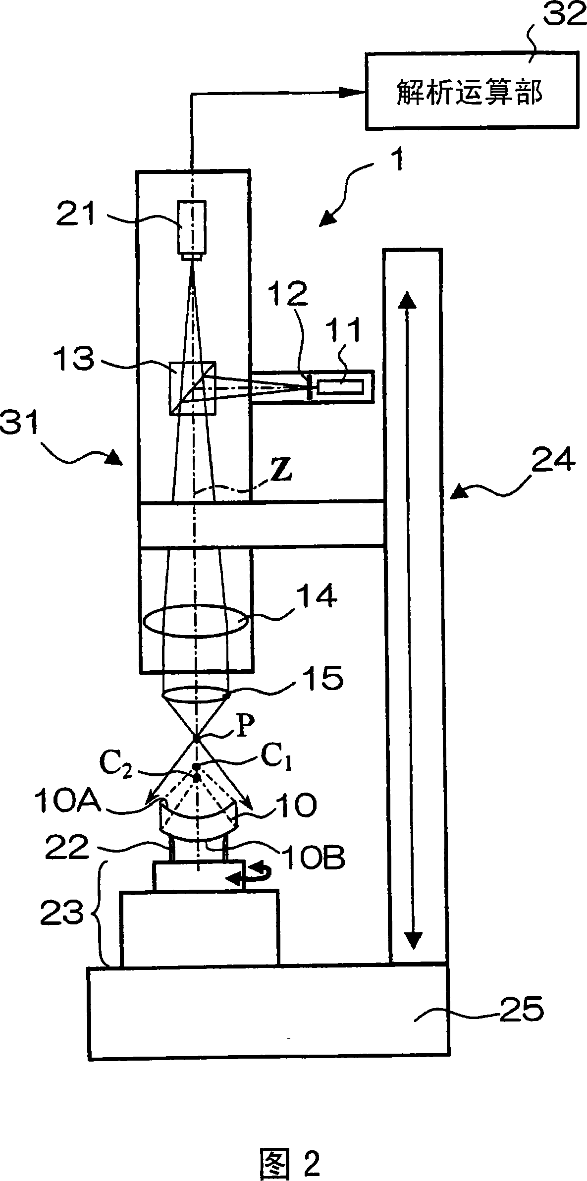
[0040] First, based on FIG. 2 , a schematic configuration of a reflection-type eccentricity measurement device for implementing the eccentricity measurement method according to an embodiment of the present invention will be described.

[0041] This eccentricity measurement device 1 is a device for measuring the eccentricity of the lens 10 to be inspected, and has: a light source 11 that irradiates light to an upper surface 10A and a lower surface 10B that become the inspection surface; a reticule plate 12, It transmits the light beam from the light source 11 and has a cross-shaped slit; and an optical system 31 for measurement. The measuring optical system 31 is provided with: a beam splitter 13 for reflecting the light from the index plate 12 approximately at a right angle; a collimator lens 14 for making the incident light beam into a parallel beam...


PUM


Abstract

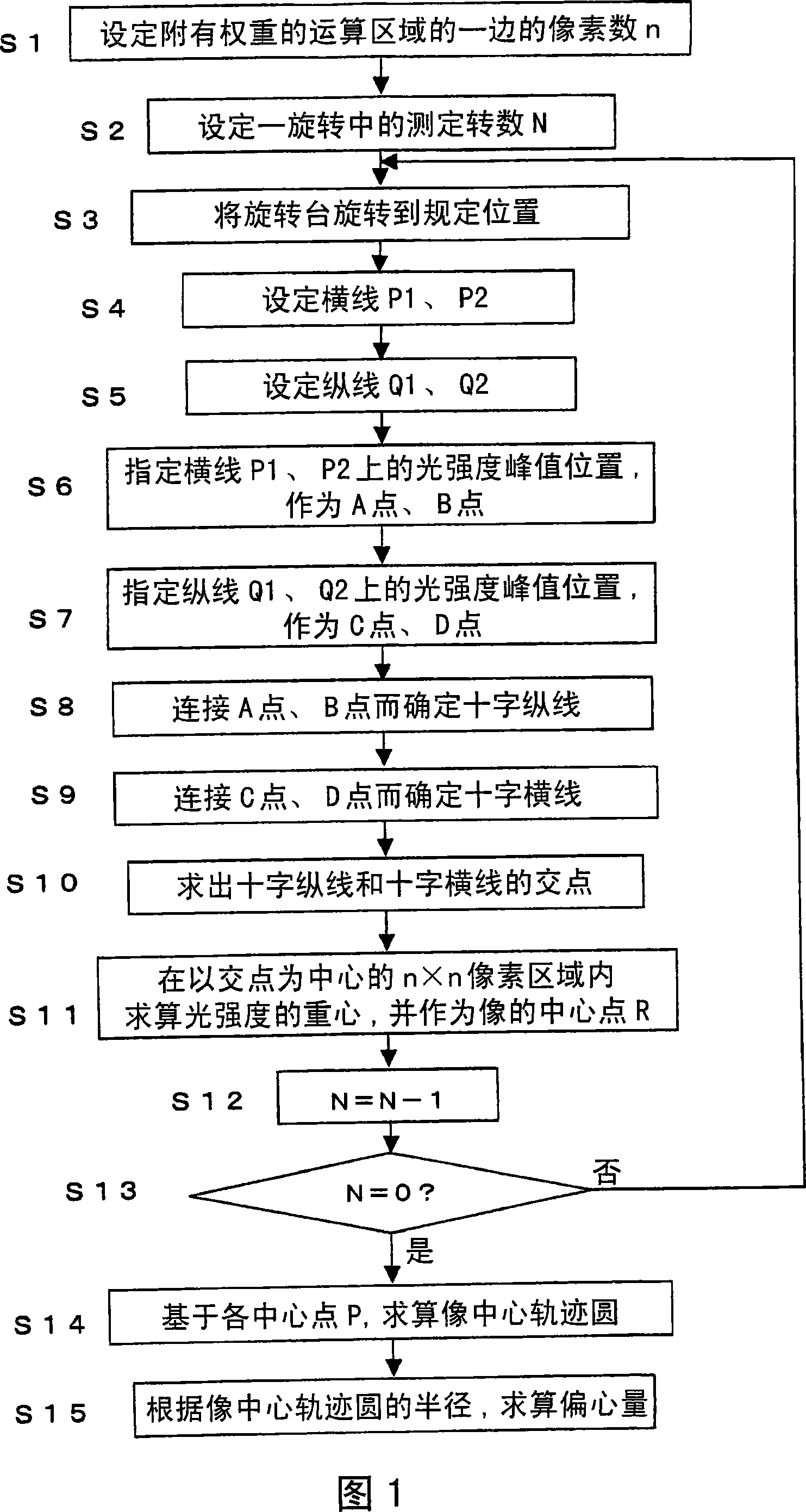
The invention discloses a measuring method of eccentricity. A detected lens (S3) is set at a preset rotating angle, and transversal line (P1,P2)(S4) crosses with image ordinate of reticule, and ordinate (Q1,Q2)(S5) crosses with image transversal line of reticule, and the peak position A, B of light intensity on the transversal line (P1,P2) and the peak position C, D of light intensity on the ordinate (Q1,Q2) is specified. The cross ordinate for connecting A and B is determined and the cross transversal line (S8,S9) for connecting C and D is also determined. Then, the crossing point of the cross ordinate and cross transversal line is specified to be as center R(S11) of reticule image. Each center R is based on multi rotating positions, the image center tracking circle (S14) is calculated and the radius of the image center tracking circle is used as eccentricity Ec(S15) of the detected surface. Therefore, in the measuring method of eccentricity using autocollimation method, the measurement precision is greatly raised in simple structure.

Description

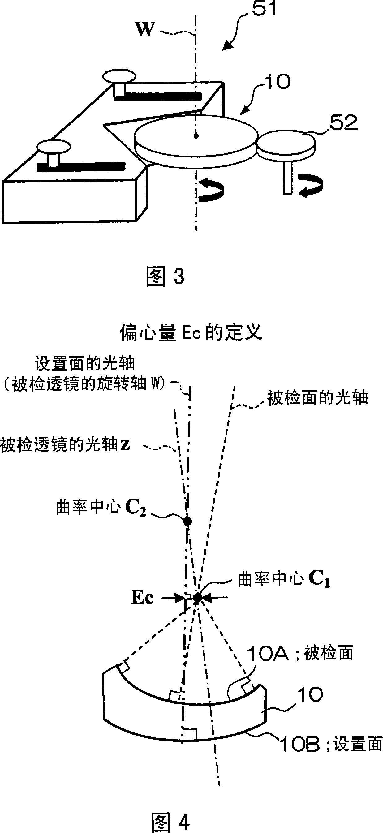
technical field [0001] The invention relates to a method for measuring the eccentricity of an inspected surface of an optical element such as a lens. Background technique [0002] As an important item in the evaluation and inspection of lenses, there is the measurement of the decentering amount of the lens surface. [0003] The amount of eccentricity of the lens surface is represented by the amount of misalignment between the center of curvature of the lens surface and their central axes. [0004] As a method of measuring such an amount of eccentricity, a method called "autocollimation" disclosed in Patent Document 1 below is known. For example, the eccentricity measuring device shown in FIG. 8 is a device provided for a reflection-type eccentricity measuring method for automatic alignment, and it is provided with: the lens to be inspected (spherical lens) 110 is rotatably centered on its central axis. A base 122 provided; a light source 111; an index plate (pinhole: pinho...

Claims


Application Information

Patent Timeline
IPC IPC(8): G01B11/27
CPCG01M11/0221G01M11/0264G01M11/00G01M11/02
Inventor 孙萍斋藤隆行
Owner FUJI PHOTO OPTICAL CO LTD
Learn More