Object image coordinate error regulation device and method when spicing surface flaw detecting image

A technology for detecting image and coordinate errors, which is applied in the field of image coordinate error adjustment devices for surface defect detection and image splicing, and can solve the problem of automatic detection and digital evaluation of surface defects without large-diameter components, which affects the correct evaluation of optical component surface defects , geometric parameter deviation and other problems, to achieve the effect of accurate defect parameter evaluation, calculation and adjustment, fast and accurate, and precise deviation angle

Active Publication Date: 2007-12-12
ZHEJIANG UNIV
View PDF0 Cites 17 Cited by
  • Summary
  • Abstract
  • Description
  • Claims
  • Application Information

AI Technical Summary

Problems solved by technology

However, these two coordinates may not match before accurate error analysis and adjustment, and are introduced into the scanned sub-aperture array, and these errors will continue to increase with the growth of the scanning trajectory. Accumulation, resulting in varying degrees of pixel misalignment during sub-aperture stitching. When the aperture to be inspected is larger, that is, the number of image frames stitched by sub-aperture is more, and the stitching error introduced by pixel misalignment is greater, making surface defects The deviation of the geometric parameters will affect the correct evaluation of the surface defects of the optical components by the whole system
[0004] At present, the commonly used detection methods for surface defects at home and abroad only realize the qualitative and statistical analysis of small-area defects, and there is no automatic detection and digital evaluation of large-diameter component surface defects.

Method used


Image

  • Object image coordinate error regulation device and method when spicing surface flaw detecting image
  • Object image coordinate error regulation device and method when spicing surface flaw detecting image
  • Object image coordinate error regulation device and method when spicing surface flaw detecting image

Examples


Embodiment

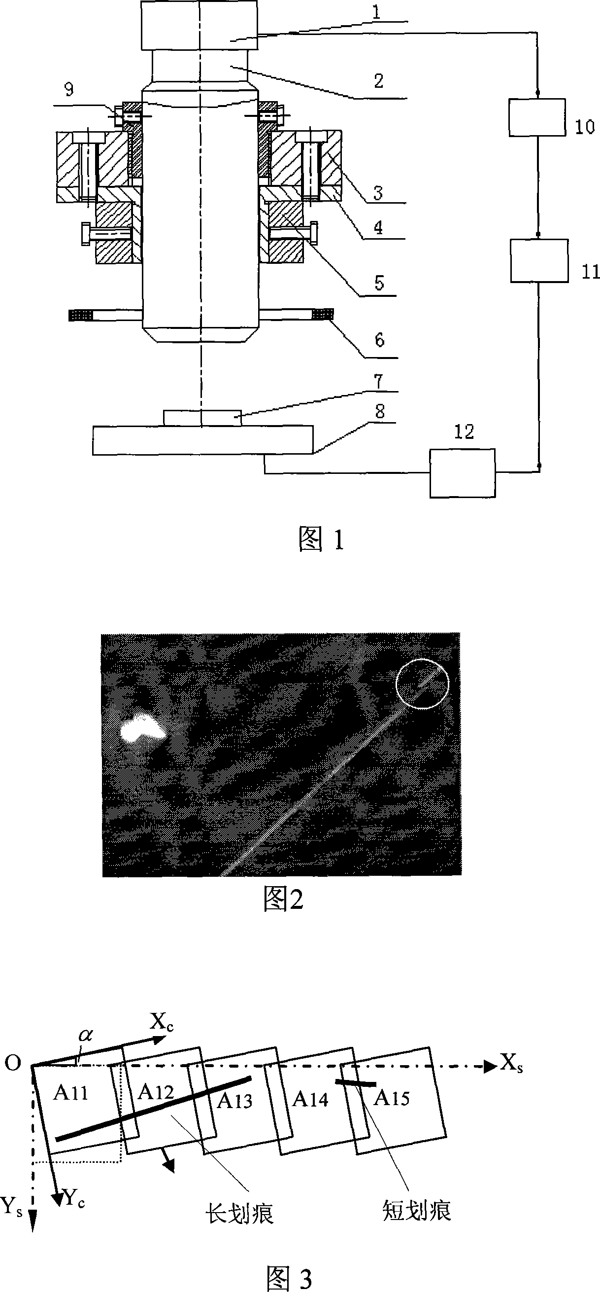
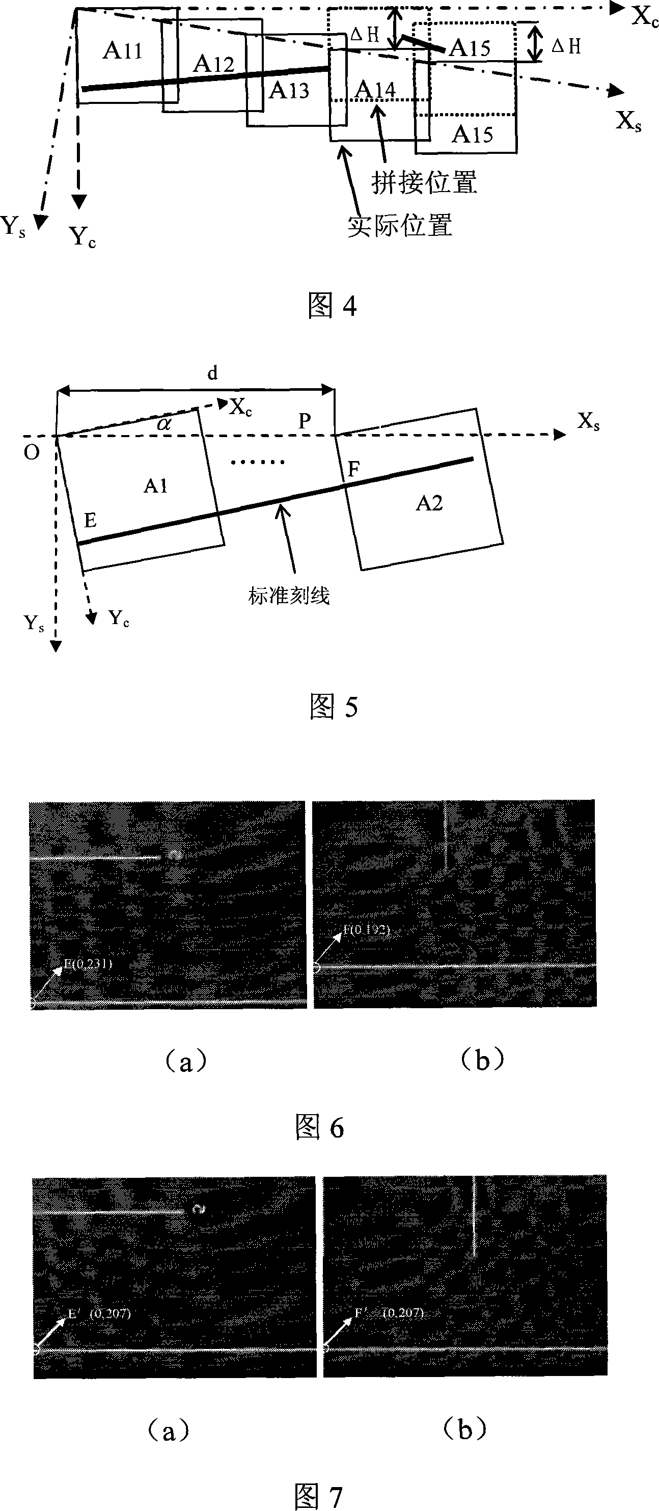
[0052] The adjustment and detection of the two coordinate systems are carried out for the error (the angle α between the CCD coordinates and the scanning track coordinates) that affects the alignment of the sub-apertures. In the detection, the size of the sub-aperture is 320×240 pixels, the system scanning positioning accuracy of the XY axis is 1um, the minimum object field of view is 2.875mm×2.168mm, and the length of the standard line is 30mm.

[0053] According to the above steps, when the standard line and the X of the CCD c Axis-parallel post-acquisition sub-aperture A 1 , and then the scanning system moves d=20mm to collect the sub-aperture A 2 , Figure 6 is the sub-aperture A collected before coordinate adjustment 1 、A 2 , it can be seen from the figure that due to the deviation of the two coordinates, the same standard line has deviated in the Y-axis direction, and the standard line and the sub-aperture A 1 、A 2 The intersection coordinates E and F are (0, 231), (...


PUM


Abstract

The invention relates to the coordinate error adjustment device and method in the jointing of surface default testing image. It joints the image of hundreds of caliber image using digital image treatment. It proposes the way of determination of the maximum angular tolerance alpha max, based on the tested caliber component dimension, viewing filed size and caliber number NXN aiming at the whole caliber jointing error, CCD coordinate and scanning track coordinate included angle alpha .It designs the angular adjustment structure to realize the consistence adjustment of the CCD coordinate system and the scanned track coordinate system. It uses the standard mark line standard plate, XY scanning system and special image processing software combination to realize the specific adjustment method with the included angle of two coordinates less than alpha max, ensures the right joint caliber to achieve the default degree and position accuracy.

Description

technical field [0001] The invention relates to an object image coordinate error adjustment device and method during surface defect detection image splicing. Background technique [0002] Surface defect detection is one of the main items in the quality inspection of precision components. With the development of modern optical technology, the surface quality requirements of some components such as optical component integrated circuits are getting higher and higher, especially for the surface defects of some high-precision optical components used in optical systems. . A large number of large-diameter precision components are used in many fields. The existence of various defects such as surface defects, scratches, and broken edges of these components will cause different degrees of scattering, which will seriously affect the normal operation of the entire system. Since the defects required to be detected by large-diameter precision components are required to reach the order o...

Claims


Application Information

Patent Timeline
Patent Type & Authority Applications(China)
IPC IPC(8): G01N21/956G01R31/308G06F19/00G06F19/18
Inventor 杨甬英刘东刘旭卓永模
Owner ZHEJIANG UNIV
Why Eureka
Try Eureka