Process of making cutting mechanism of baler

A cutting mechanism and manufacturing process technology, applied in metal processing, paper/cardboard containers, containers, etc., can solve the problems of supporting design that is not conducive to diversified functions, damage to workpieces, inconvenient maintenance and replacement, etc., so as to facilitate maintenance and replacement, conception Ingenious and reasonable workmanship

Inactive Publication Date: 2007-12-19
SHANGHAI LIYI ELECTRIC
View PDF0 Cites 0 Cited by
  • Summary
  • Abstract
  • Description
  • Claims
  • Application Information

AI Technical Summary

Problems solved by technology

Its defect is: once the workpiece serving for cutting is damaged, it is not easy to repair and replace
In addition, it is not conducive to the supporting design of the mechanism's diversified functions

Method used


Image

  • Process of making cutting mechanism of baler

Examples


Embodiment Construction

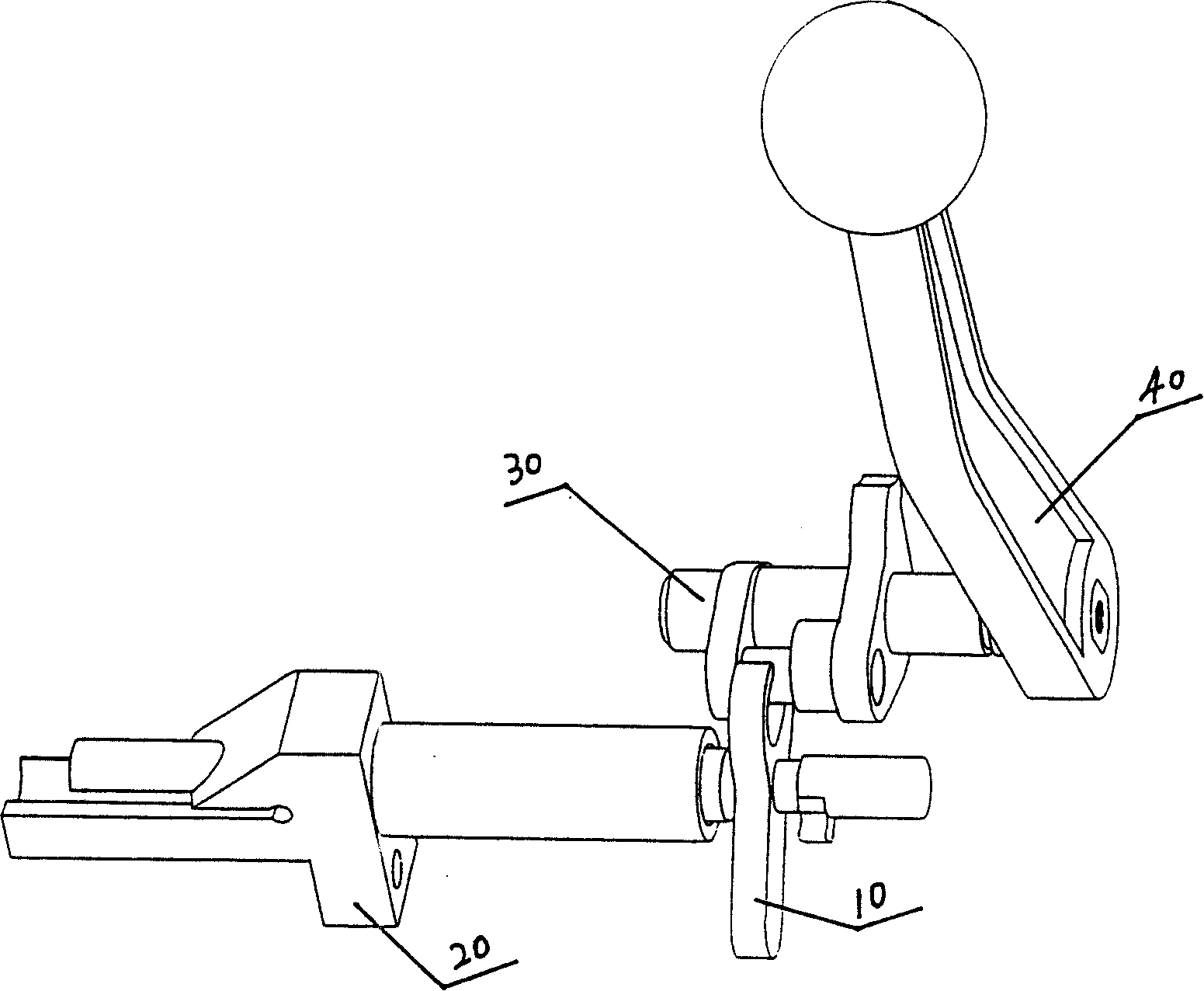
[0008] A manufacturing process of a cutting mechanism of a baler mainly includes the following steps: A. providing a cutting knife, which is arranged on a cutting knife holder, and the cutting knife is connected with a camshaft through a shift fork; B. providing a camshaft whose Shaft ends are provided with cut strap handles. The structure of the cutting mechanism of the baler manufactured by the present invention will be described in further detail below in conjunction with the accompanying drawings. Referring to accompanying drawing, a kind of cutting mechanism of packing machine, cutting knife 10 is arranged on cutting knife frame 20, and cutting knife 10 is connected with camshaft 30 by shift fork, and the shaft end of camshaft 30 is covered with cutting handle 40. When it is matched with the baler, it is only necessary to fix the cutter frame on the bottom plate of the baler and make the camshaft pass through the wall plate of the baler. Since the mechanism is an indepen...


PUM


Abstract

The process of making cutting mechanism of baler includes the following steps: 1. assembling one cutter on the cutter holder and connecting the cutting with the cam shaft through one shift fork; and 2. assembling one cam shaft and one belt cutting handle in its one end. The present invention has reasonable technological process, and the cutting mechanism of baler has fluent cutting and easy maintenance and replacement.

Description

technical field [0001] The invention relates to the technical field of packing machinery, in particular to a manufacturing process of a device for cutting packing tape during packing. Background technique [0002] At present, all kinds of balers on the market do not have a separate cutting mechanism. Its defect is: once the workpiece serving for cutting is damaged, it is not convenient for maintenance and replacement. In addition, it is unfavorable for the supporting design of the functional diversification of this mechanism. Contents of the invention [0003] The object of the present invention is to provide a manufacturing process for an independent cutting mechanism that can effectively overcome the above-mentioned defects and is matched with a baler and is convenient for maintenance and replacement of damaged workpieces. [0004] In order to achieve the above object, the present invention adopts the following technical solutions: a manufacturing process of a cutting ...

Claims


Application Information

Patent Timeline
IPC IPC(8): B65B13/04B26D5/10
Inventor 史朝敏夏医方高云
Owner SHANGHAI LIYI ELECTRIC
Why Eureka
Try Eureka