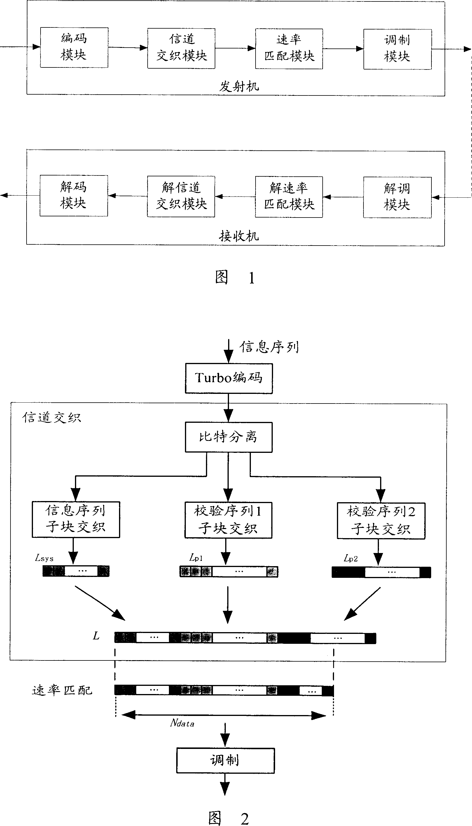
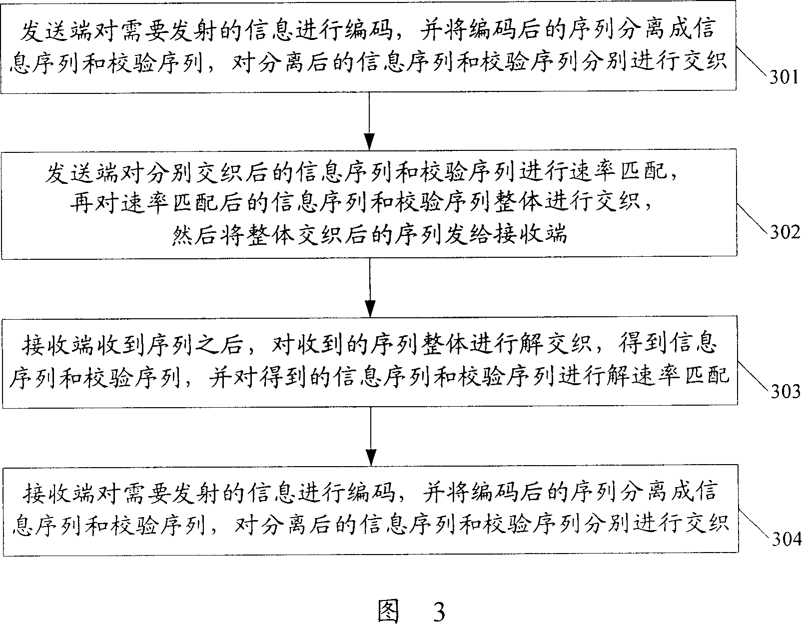
Method and system for transmitting information
A technology for transmitting information and information sequences, which is applied in the field of transmitting information, and can solve problems such as performance loss, inability to recover information, and affecting decoding at the receiving end
- Summary
- Abstract
- Description
- Claims
- Application Information
AI Technical Summary
Problems solved by technology
Method used
Image
Examples
Embodiment 1
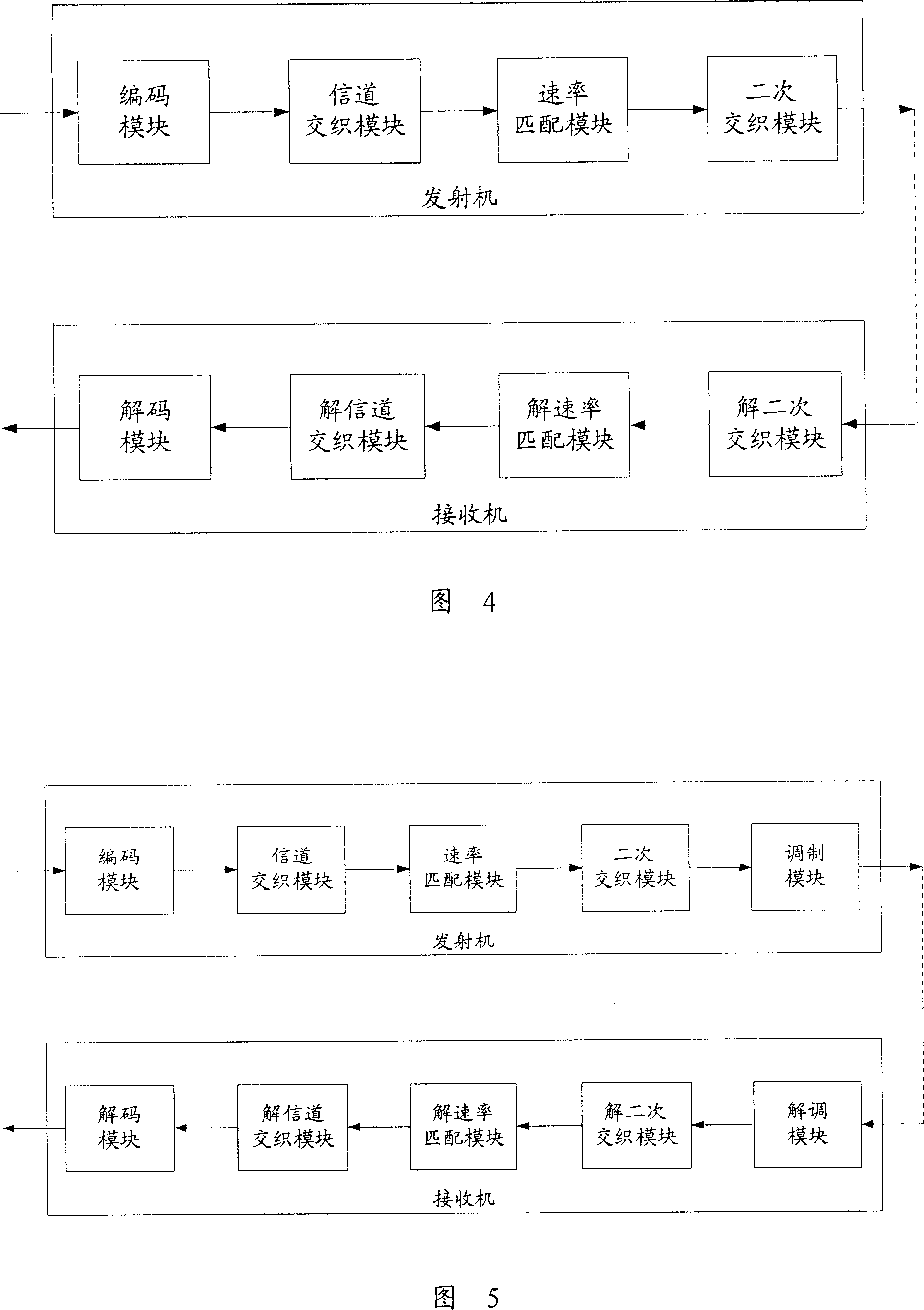
[0082] As shown in Figure 5, the modulation module in the transmitter is located after the secondary interleaving module, wherein the secondary interleaving module is used to send the overall interleaved sequence to the modulation module; the modulation module is used to modulate the received sequence, And send out the modulated sequence.
[0083] Corresponding to the position of the modulation module, the demodulation module in the receiver is located before the de-secondary interleaving module, wherein the demodulation module is used to demodulate the received sequence and send the demodulated sequence to the de-secondary Secondary interleaving module.
[0084] Referring to Figure 6, the method for transmitting information corresponding to the transmitter structure shown in Figure 5 mainly includes the following steps:
[0085] Step 601: The transmitter encodes the information that enters itself and needs to be transmitted, and the encoded sequence includes information bits...
Embodiment 2
[0101] As shown in Figure 9, the modulation module is located between the channel interleaving module and the rate matching module, wherein the channel interleaving module is used to send the interleaved information sequence and check sequence to the modulation module; the modulation module is used for receiving The information sequence and the check sequence are modulated, and the modulated information sequence and check sequence are sent to the rate matching module.
[0102] The demodulation module is located between the de-rate matching module and the de-channel interleaving module, wherein the de-rate matching module is used to send the de-rate-matched information sequence and check sequence to the demodulation module; The information sequence and the check sequence are demodulated, and the demodulated information sequence and the check sequence are sent to the channel deinterleaving module.
[0103] Referring to Figure 10, the method for transmitting information correspon...
Embodiment 3
[0116] As shown in Figure 12, the modulation module is located between the rate matching module and the secondary interleaving module, wherein the rate matching module is used to send the rate-matched information sequence and check sequence to the modulation module; the modulation module is used to send the received The information sequence and check sequence are modulated, and the modulated information sequence and check sequence are sent to the secondary interleaving module.
[0117] The demodulation module is located between the de-secondary interleaving module and the de-rate matching module, wherein the de-secondary interleaving module is used to send the obtained information sequence and check sequence to the demodulation module; the demodulation module is used to process the received information Demodulate the sequence and check sequence, and send the demodulated information sequence and check sequence to the de-rate matching module.
[0118] Referring to Figure 13, the...
PUM
 Abstract
Description
Claims
Application Information
 - R&D
- Intellectual Property
- Life Sciences
- Materials
- Tech Scout
- Unparalleled Data Quality
- Higher Quality Content
- 60% Fewer Hallucinations
Browse by: Latest US Patents, China's latest patents, Technical Efficacy Thesaurus, Application Domain, Technology Topic, Popular Technical Reports.
© 2025 PatSnap. All rights reserved.Legal|Privacy policy|Modern Slavery Act Transparency Statement|Sitemap|About US| Contact US: help@patsnap.com


