Three-dimensional control channel beams

A three-dimensional control and beam technology, applied in the direction of telephone communication, electrical components, branch office equipment, etc.

Inactive Publication Date: 2007-12-26
INTERDIGITAL TECH CORP
View PDF1 Cites 24 Cited by
  • Summary
  • Abstract
  • Description
  • Claims
  • Application Information

AI Technical Summary

Problems solved by technology

[0033] The traditional wireless communication systems described above are limited to adjusting th

Method used


Image

  • Three-dimensional control channel beams
  • Three-dimensional control channel beams
  • Three-dimensional control channel beams

Examples


Embodiment Construction

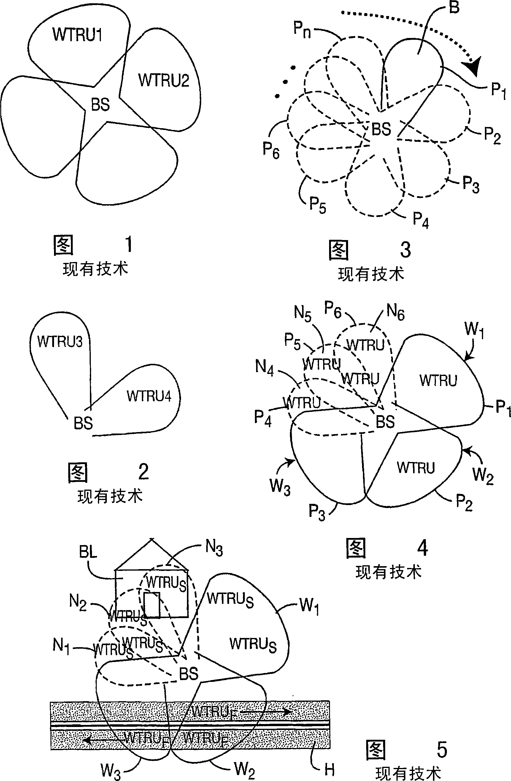
[0065] Hereinafter, the term "WTRU" includes, but is not limited to, user equipment (UE), mobile station, fixed or mobile subscriber unit, pager, or any other type of component operable in a wireless environment.

[0066] Hereinafter, the term "base station" includes, but is not limited to, a Node B, a site controller, an access point (AP) or any other interfacing device in a wireless environment.

[0067] The present invention can be incorporated into wireless communication systems, wireless transmit / receive units and base stations. The inventive features may be incorporated into an integrated circuit (IC) or configured in a circuit comprising multiple interconnected components.

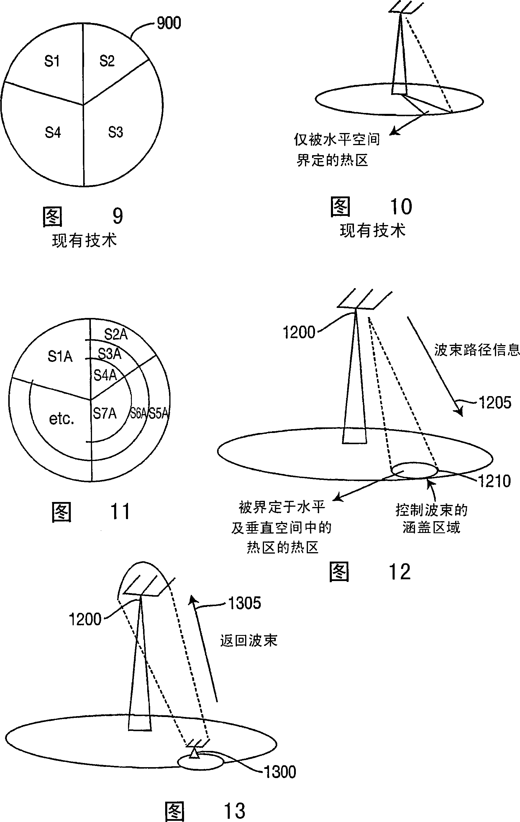
[0068] In one embodiment, the vertical beam angle information obtained from the smart antenna is used for sector separation and cell planning. Unlike sectors S1, S2, S3, S4 shown in Fig. 9, sectors are created in the cell coverage area by including horizontal angle information and vertical beam ang...


PUM


Abstract

A wireless communication system and method generates and shapes one or more three-dimensional control channel beams for transmitting and receiving signals. Each three-dimensional beam is directed to cover a particular coverage area and beam forming is utilized to adjust bore sight and beam width of the three-dimensional beam in both azimuth and elevation, and the three-dimensional control channel beam is identified. In another embodiment, changes in hot-zones or hot-spots, (i.e., designated high volume user coverage areas), are managed by a network cell base station having at least one antenna. Each of a plurality of wireless transmit/receive units (WTRUs) served by the base station use a formed beam based on one or more beam characteristics. When the coverage area is changed, the base station instructs at least one of the WTRUs to change its beam characteristics such that it forms a return beam concentrated on the antenna of the base station.

Description

technical field [0001] The present invention relates to wireless communication systems. More particularly, the present invention relates to implementing smart antenna beam coverage in azimuth and elevation planes to provide enhanced wireless services in concentrated coverage areas by forming and steering 3D control channel beams. Background technique [0002] Conventional wireless communication systems typically operate in two states. One is used to provide initial contact and ongoing overall control of the communication device. The other is the data state during which data is exchanged. The systems have different functions and therefore have different coverage, capacity, availability, reliability and data rate requirements. Improving one or more of these features would help. [0003] U.S. Patent No. 6,785,559 issued August 31, 2004 to Goldberg et al., which is hereby incorporated by reference in its entirety, is entitled "System for Efficient Coverage Cell Separation Us...

Claims


Application Information

Patent Timeline
IPC IPC(8): H04M1/00
Inventor 史蒂文・J・高伯格费堤・欧兹鲁特潘俊霖蔡寅铭
Owner INTERDIGITAL TECH CORP
Why Eureka
Try Eureka