Chamber assembly for application in electron beam machining

A technology of electron beam processing and chamber body, applied in electron beam welding equipment, metal processing equipment, manufacturing tools, etc., can solve the problems of time-consuming and difficult

Inactive Publication Date: 2008-01-02
ALL WELDING TECH
View PDF2 Cites 2 Cited by
  • Summary
  • Abstract
  • Description
  • Claims
  • Application Information

AI Technical Summary

Problems solved by technology

[0004] It is often difficult and time-consuming to change workpieces through small holes in the chamber, especially when welding small workpieces in small chambers

Method used


Image

  • Chamber assembly for application in electron beam machining
  • Chamber assembly for application in electron beam machining
  • Chamber assembly for application in electron beam machining

Examples


Embodiment Construction

[0047] Some methods for electron beam processing, such as electron beam generators, deflection coils, etc., that can be installed near or in the housing of the chamber are not described in the drawings.

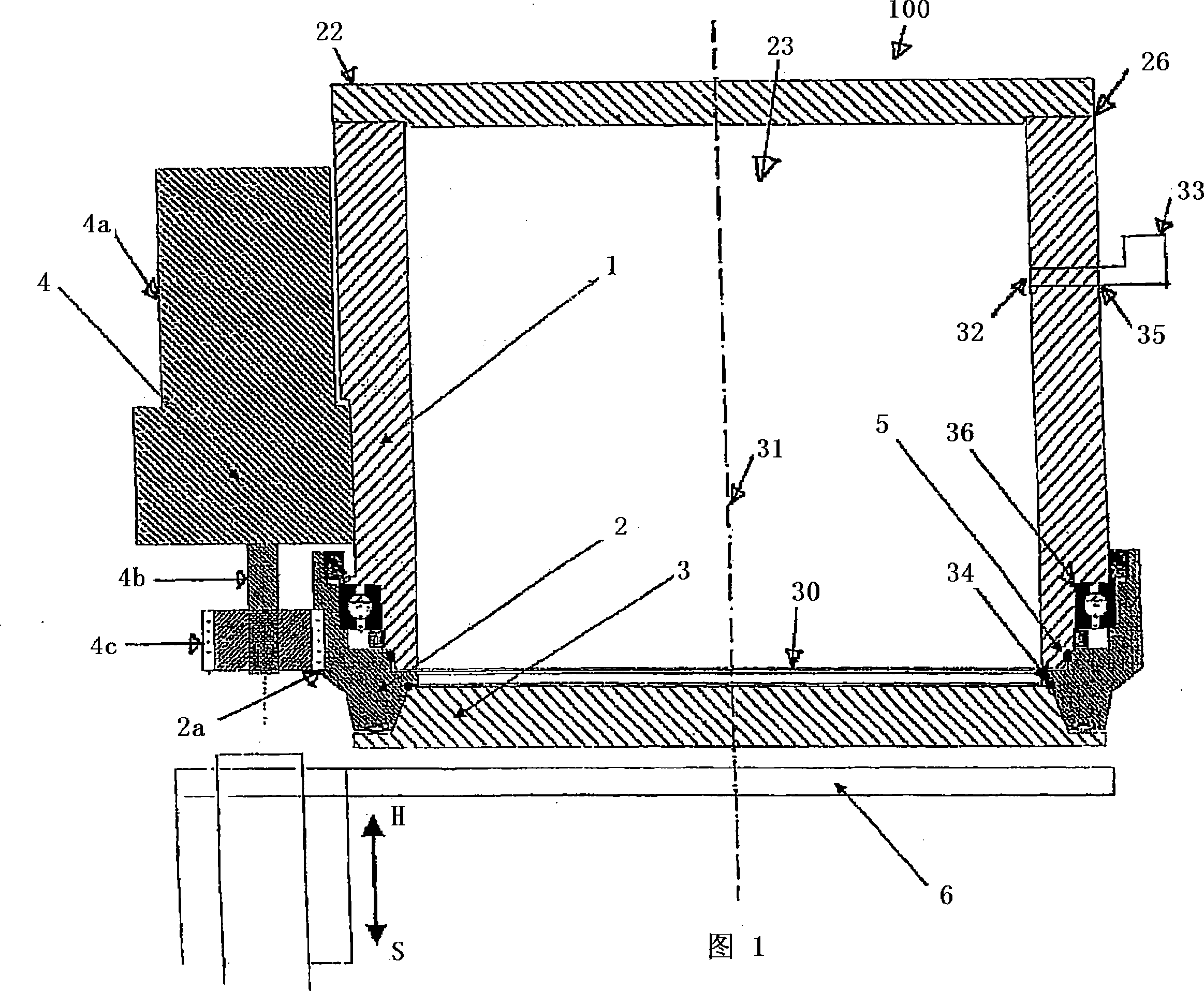
[0048]Figure 1 shows the first embodiment of the chamber device 100. According to the first embodiment, the chamber device includes a chamber housing 26, which defines a chamber space 23. Electron beam processing can be carried out in the chamber space, such as vacuum electron beam workpiece welding. In this embodiment, the chamber housing 26 includes a cylindrical chamber wall 1, a cover 22, and a feeding / outlet hole 30. The cylindrical axis of the chamber wall 1 defines the longitudinal axis of the chamber space 23. The cover 22 forms the upper boundary of the chamber space 23 in the longitudinal direction. A feed / out hole 30 is formed on the bottom surface of the chamber body shell 26 in the longitudinal direction, the shape of which is circular, and the diameter is the same a...


PUM


Abstract

The invention discloses a chamber assembly for application in electron beam machining. The said chamber assembly is used to perform electron beam welding on the workpiece in vacuo, comrprising a shell for defining a chamber space, including at least one intake / outtake hole, and a circular ring, wherein the circular ring encloses along the intake / outtake hole and is torred above the shell to make it rotate along the shaft corresponding to intake / outtake hole, and a chamber cover connected with the circular ring and for capping the intake / outtake hole and the chamber cover rotates together with the circular ring corresponding to intake / outtake hole.

Description

Technical field [0001] The invention relates to a chamber body device used for electron beam processing, particularly applicable to the welding of electron beam workpieces in vacuum, and particularly relates to a machine with a small chamber body. Background technique [0002] Electron beam processing, such as electron beam welding of workpieces, is usually carried out in some chambers, in which there are some workpiece holders. The workpieces are sent to these holders, and then put down after passing through a closable hole on the chamber body. [0003] When welding between the welding device and the workpiece, some corresponding movement is required, such as movement by the magnetic deflection of the electron beam, or movement by moving the electron beam generator, or using a push rod with one or more shafts To move the workpiece to produce movement, or use the above methods to produce movement at the same time. [0004] It is usually difficult and time-consuming to replace wor...

Claims


Application Information

Patent Timeline
Patent Type & Authority Applications(China)
IPC IPC(8): B23K15/00B23K15/06
CPCB23K15/06
Inventor 法兰兹·沃库卡
Owner ALL WELDING TECH
Why Eureka
Try Eureka