Washing machine

A technology for washing machines and washing tanks, which is applied in the field of washing machines, and can solve the problems of reduced operating efficiency of heat pumps, difficulties in heating up the condenser, and heating up of tap water, etc.

Inactive Publication Date: 2008-01-02
TOSHIBA LIFESTYLE PROD & SERVICES CORP
View PDF9 Cites 5 Cited by
  • Summary
  • Abstract
  • Description
  • Claims
  • Application Information

AI Technical Summary

Problems solved by technology

Therefore, the operating efficiency of the heat pump is greatly reduced, and it becomes more difficult to raise the temperature of the condenser.
Generally speaking, when the water temperature rises from normal temperature by about 5°C, the washing ability of the clothes will be fully improved, but if only the tap water in the water pipe is heated by the condenser, it is difficult to "25L (liter) ~ 30L" at this level. "The amount of tap water warmed up to the temperature suitable for washing

Method used


Image

  • Washing machine
  • Washing machine
  • Washing machine

Examples


Embodiment 1

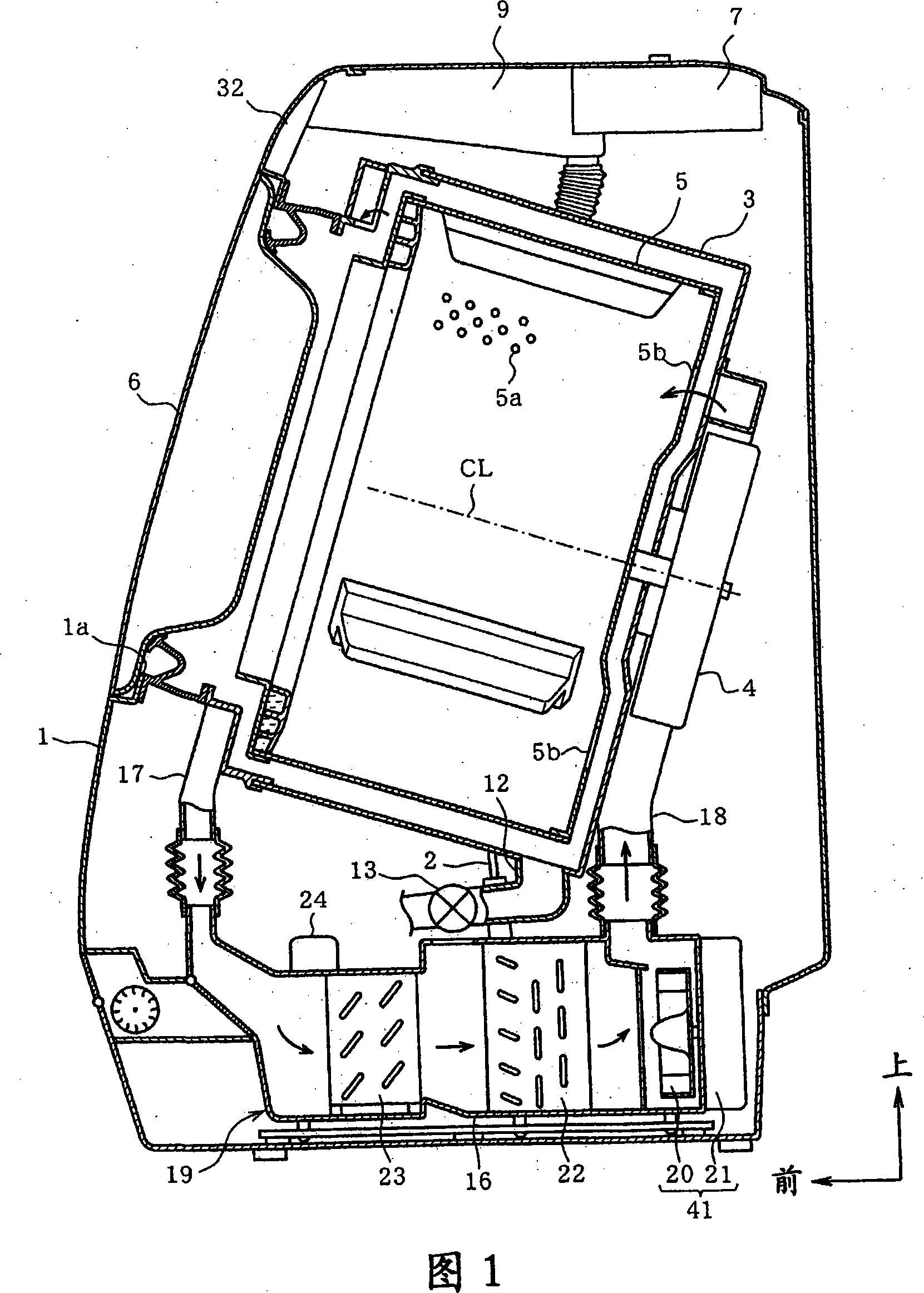
[0033] Inside the outer case 1 , as shown in FIG. 1 , a plurality of dampers 2 are accommodated. A water tank 3 is fixed to rods of the plurality of dampers 2 , and the water tank 3 is accommodated inside the outer case 1 in a damped state and a buffered state via the plurality of dampers 2 . The water tank 3 is in the shape of a bottomed cylinder with the rear closed, and is arranged in an inclined state with the axis line CL being high at the front and low at the rear. On the rear plate of the water tank 3 , a stator of a drum motor 4 is fixed outside the water tank 3 . The drum motor 4 includes an outer rotor type DC brushless motor in which a rotor is disposed on the outer periphery of a stator, and the rotating shaft of the drum motor 4 protrudes into the water tank 3 .

[0034] A drum (drum) 5 is fixed to the rotation shaft of the drum motor 4 . The drum 5 corresponds to a washing tank. By operating the drum motor 4 , it rotates integrally with the rotating shaft of t...

Embodiment 2

[0079] A three-way valve 45 is connected to the discharge port of the compressor 24 as shown in FIG. 8 . The three-way valve 45 is driven by a valve solenoid including an electromagnetic solenoid. The three-way valve 45 can make the refrigerant discharged from the compressor 24 flow into the separate condenser 26 and the separate condenser 22 respectively, and prevent the refrigerant discharged from the compressor 24 from flowing into the separate condenser 26. Flow into the split condenser 22 switches between dry states.

[0080] FIG. 9 shows the control content of the control circuit 34 when the hot water washing course is set. The CPU of the control circuit 34 switches the water supply valve 7 from the cold water injection state to the water injection stop state in step S7 when there is normal temperature tap water at the water injection interruption level in the water tank 3 . Then, in step S8, the three-way valve 45 is switched to the water injection state, in step S9, ...

Embodiment 3

[0084] Inside the main duct 16 , as shown in FIG. 10 , a corrugated finned condenser 50 is housed. The condenser 50 is configured such that a plurality of fins are interposed between linear portions of one refrigerant pipe in a serpentine shape, and the plurality of fins are respectively joined to the linear portions of the refrigerant pipe. FIG. 11( a ) shows the piping state of the condenser 50 . The refrigerant tubes 51 of the condenser 50 are arranged in four rows in the left-right direction. One water pipe 52 in a serpentine shape is joined to a plurality of fins of the condenser 50 . The water pipes 52 are arranged in two rows in the left-right direction. The inner surface of the water pipe 52 is formed of a smooth surface as shown in FIG. 11( b ). Each row of the water pipes 52 is interposed between the rows of the refrigerant pipes 51 as shown in FIG. This water pipe 52, as shown in Figure 10, is connected on the heating outlet of water supply valve 7 via water pip...


PUM


Abstract

The objective of the invention is to raise the water temperature to the temperature which is suitable for washing. Injecting the tap water with ordinary temperature to the water storage tank by the water pipe (8), heating the tap water in the water storage tank (2) by operating the heat pump (43) to inject the hot wind to the water storage tank. The temperature of the condenser (26) has become enough high comparing with the beginning of hot wind injection treatment after a preset time from injecting hot wind for treating, injecting the tap water to the water storage tank through the water pipe (10) when the temperature of the condenser (26) has reached a high enough temperature. Therefore, the tap water in the water pipe (10) is warmed on a large scale as the water has absorbed the thermal capacity of the condenser (26) itself thereby raising the water temperature to the temperature which is suitable for washing.

Description

technical field [0001] The present invention relates to a washing machine having a heat pump as a drying mechanism for drying clothes in a washing tub. Background technique [0002] For example, Japanese Patent No. 3330789 and Japanese Patent Laying-Open No. 2006-87484 disclose a washing machine, which is constructed by heating the electric heater (electric heater) directly installed in the water tank to make the water stored in the tank The tap water in the sink becomes hot. In the case of such a configuration, the water tank is directly heated by the electric heater, so there is a problem that the water tank becomes high temperature. In addition, since the heater is exposed to a humid environment, there are problems of electric leakage and short-circuit. [0003] The above-mentioned various problems can be solved by using a heat pump system (heat pump system) as a heat source, making the condenser of the heat pump and the water pipe that injects tap water into the water ...

Claims


Application Information

Patent Timeline
Patent Type & Authority Applications(China)
IPC IPC(8): D06F25/00D06F39/00D06F39/04D06F58/10D06F58/20D06F58/28
Inventor 鹿岛弘次西胁智井奥辰夫
Owner TOSHIBA LIFESTYLE PROD & SERVICES CORP
Why Eureka
Try Eureka