Optical elements and imaging optics comprising them

A technology of optical components and imaging optics, which is applied in the field of diffractive or transmissive optical components and refraction, which can solve the problems of low transmittance and achieve low-cost effects

Inactive Publication Date: 2008-01-02
SCHOTT AG
View PDF5 Cites 11 Cited by
  • Summary
  • Abstract
  • Description
  • Claims
  • Application Information

AI Technical Summary

Problems solved by technology

However, the mentioned transmittance is very low

Method used


Image

  • Optical elements and imaging optics comprising them
  • Optical elements and imaging optics comprising them
  • Optical elements and imaging optics comprising them

Examples


Embodiment Construction

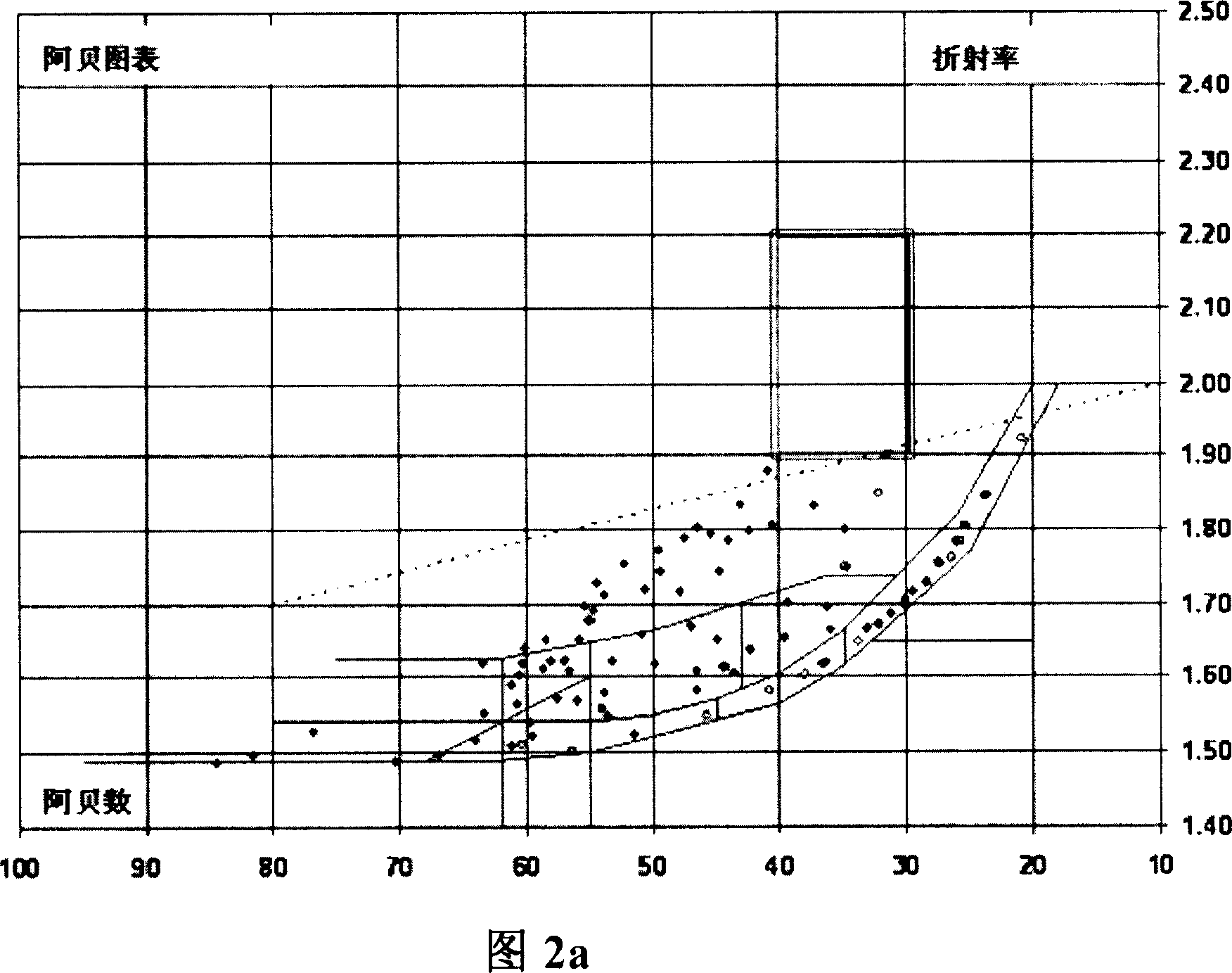
[0093] In the Abbe diagram according to Fig. 2a, the points shown as circle symbols represent exemplary types of glass that can be produced with glass melting techniques available today and of high optical quality. From Figure 2a it can be easily seen that the glass above the point line passing the point Abbe number = 80 / refractive index = 1.7 and the point Abbe number = 10 / refractive index = 2.0 can only pass through the current limited glass melting and glass Forming technology produced. Specifically, glasses in the range of refractive indices between about 1.9 and about 2.2 and Abbe numbers between about 30 and 40 tend to be unstable (see rectangles in Figure 2a). As explained below, the optoceramics according to the invention are transparent materials whose refractive index is between approximately 1.9 and 2.2, preferably between 1.9 and 2.0, and at the same time whose Abbe number is in the range between approximately 30 and 45. This offers the possibility of dechromatic ...


PUM

PropertyMeasurementUnit
birefringenceaaaaaaaaaa
diameteraaaaaaaaaa
sizeaaaaaaaaaa

Abstract

The present invention relates to the optical element of refraction, diffraction or transmission which is made of optical ceramics that has high transparency degree to the visible light and / or infrared light. Concretely speaking the invention relates to the optical element which is made of the optical ceramic that is suitable for the imaging optical element, such as the object lens which has the imaging characters of reducing the color difference and especially the apochromatism.

Description

technical field [0001] The invention relates to refractive, diffractive or transmissive optical elements made of optoceramics with high transparency for visible and / or infrared light. In particular, the invention relates to optical elements made of those optoceramics suitable for use in imaging optical elements, such as objectives with reduced chromatic aberration, especially with near apochromatic imaging properties. Background technique [0002] According to the invention, an optoceramic means a substantially single-phase polycrystalline material based on oxides and having a high degree of transparency. Therefore, optoceramics are a special subclass of ceramics. In this context, "single phase" means that in the composition of interest at least more than 95% of the material, preferably at least 97%, more preferably at least 99% and most preferably 99.5% to 99.9% of the material is crystalline form exists. The individual grains are arranged in a compact manner and, based ...

Claims


Application Information

Patent Timeline
Patent Type & Authority Applications(China)
IPC IPC(8): G02B1/00
CPCC04B2235/81C04B2235/3418C04B2235/3206C04B2235/3201G02B1/02C04B2235/3229C04B2235/3232C04B2235/9653C04B35/486C04B2235/3208C04B2235/72C04B2235/3227C04B2235/786C04B2235/762C04B2235/3203C04B2235/3224C04B2235/3225
Inventor 斯特芬·赖歇尔沃尔弗拉姆·拜尔弗兰克-托马斯·伦特斯冈野吉雄约亨·阿尔克姆佩尔若泽·齐默尔约瑟夫·S·海登卡斯滕·温霍尔德乌尔里希·波伊切尔特马丁·莱茨
Owner SCHOTT AG
Why Eureka
Try Eureka