
Movable vacuum apparatus

A vacuum device and hollow technology, which is applied in the field of side wall vacuum seals and movable vacuum devices, can solve the problems of sealing ring wear, inconvenient chamber frequent opening and closing, tearing, etc., and achieve low manufacturing cost, reduced processing accuracy and mutual With the effect of precision and applicability

Inactive Publication Date: 2008-01-09
DALIAN UNIV OF TECH
View PDF1 Cites 2 Cited by
  • Summary
  • Abstract
  • Description
  • Claims
  • Application Information

AI Technical Summary

Problems solved by technology

However, in this method, frequent opening and closing have high requirements on the processing accuracy of the upper and lower inflatable sealed chambers and the matching accuracy between them.
Moreover, when the sealing chamber is pressed into the sealing ring, it will cause a pressure shock to the equipment, and the sealing ring will be worn or even torn
[0003] U.S. patent specification US-005667224A discloses a vacuum sealing structure that can be adjusted, but although the structure can make the sealing chamber relatively movable, the device is not convenient for the frequent opening and closing of the chamber, so it is necessary to realize a vacuum seal that can be used without sealing. In the case of impact, the sealed chamber can be opened and closed quickly and frequently, and the upper and lower chambers can do relative movement after vacuum sealing to solve this problem

Method used


Image

  • Movable vacuum apparatus
  • Movable vacuum apparatus
  • Movable vacuum apparatus

Examples


Embodiment Construction

[0016] The specific implementation manner of an embodiment will be described in detail below in conjunction with the accompanying drawings.

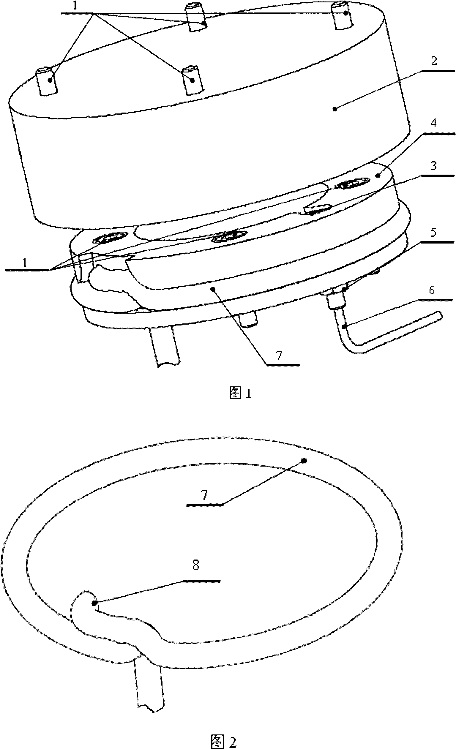
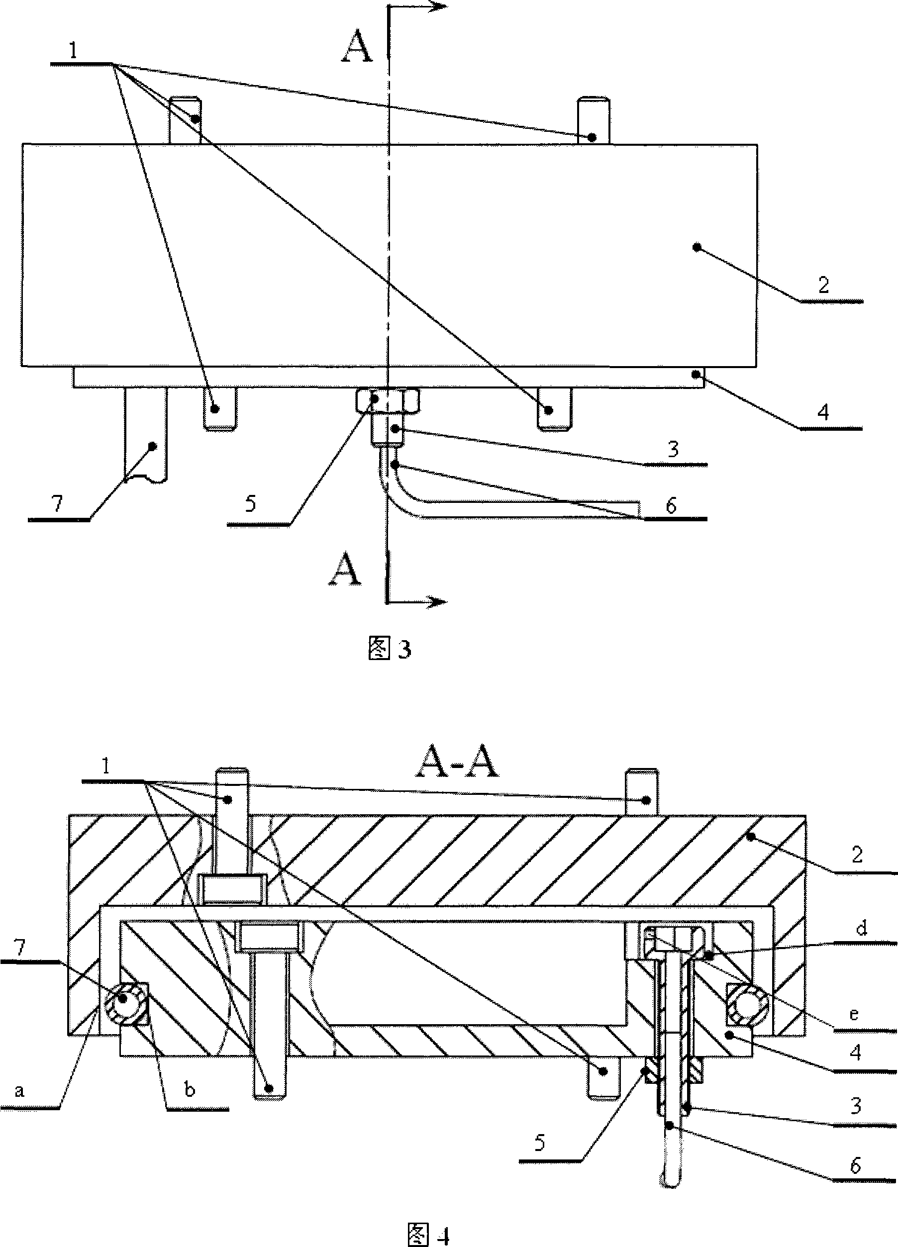
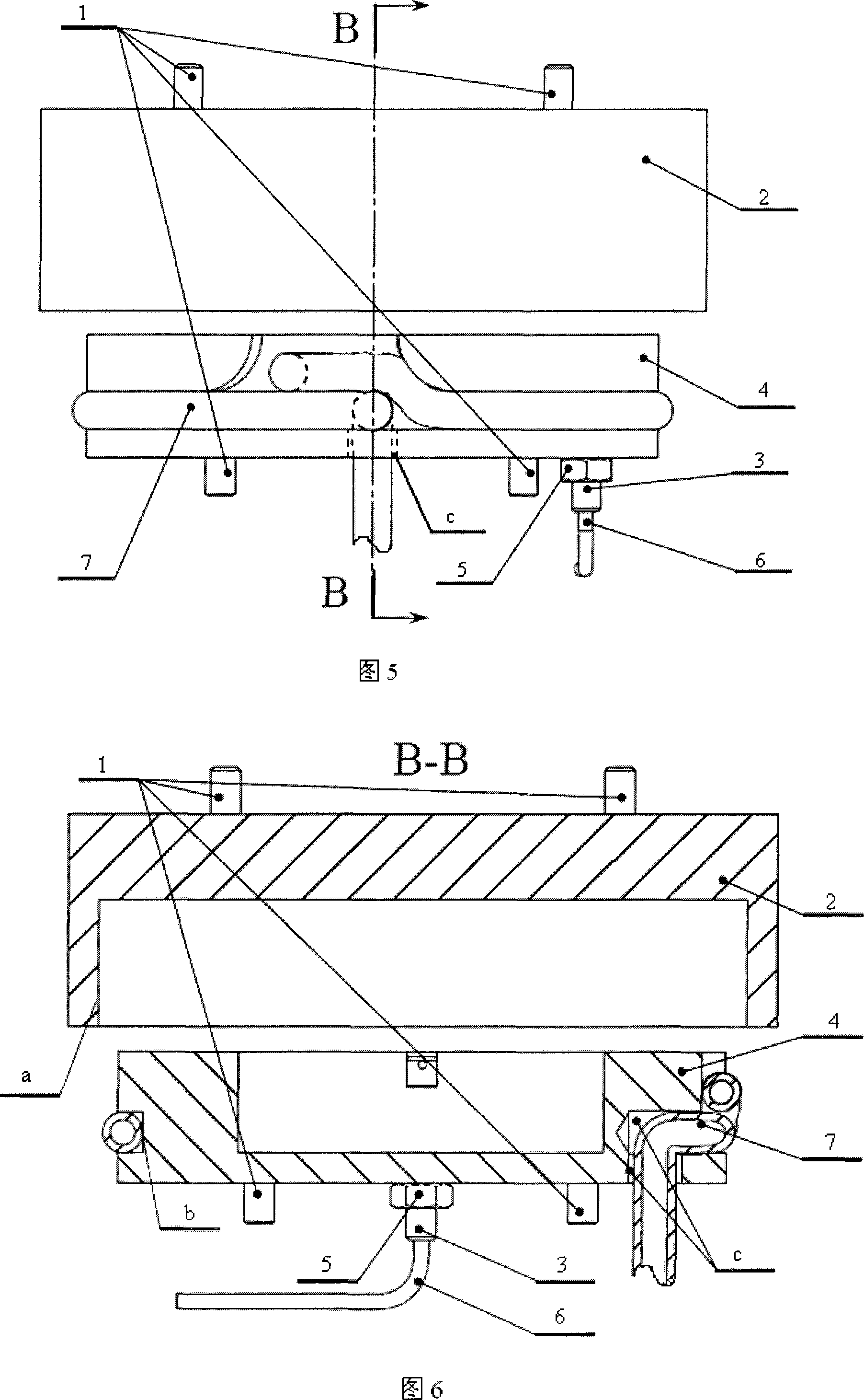
[0017] As shown in Figure 1, a movable vacuum device uses a gas-liquid hose 7 as its sealing ring to replace the O-ring usually used as a movable side wall seal. By filling the gas-liquid hose 7 with pressurized gas or The liquid expands the hose to achieve chamber sealing, and at the same time, the gas-liquid hose 7 can be used to shrink after the gas or liquid is drawn out, so that the two chambers can be separated and joined frequently and quickly.

[0018] As shown in Figures 2 and 7, the head of the hollow sealing bolt 3 is horizontally opened with a small hole e vertically connected with the inner hole, and the small hole e serves as an auxiliary vacuum. The gas-liquid hose closed end 8 of the gas-liquid hose 7 is bonded to the annular groove b of the lower sealing chamber 4, and the tube is wound counterclockwise in the annular gr...


PUM


Abstract

This invention is moveable vacuum device which belongs to vacuum sealing field. It includes upper sealing cavity, lower sealing cavity, vacuumizing pipe and gas-liquid flexible pipe. The upper sealing cavity is columnar. Its intra-cavity is ring shaped. Several inner-hexagonal machine screws, which are connected with external power source, are evenly assembled on the top plane of upper sealing cavity. The lower sealing cavity is columnar and is arranged in the intra-cavity of upper sealing cavity. Several inner-hexagonal machine screws, which are connected with external mechanism, are evenly assembled on the bottom plane of lower sealing cavity. The columnar face of lower sealing cavity has ring shaped groove. The gas-liquid flexible pipe is counter-clockwise winded around in the lower sealing cavity ring shaped groove. The cavity can open or close quickly and undertake relative movement after vacuum sealing.

Description

technical field [0001] The movable vacuum device of the present invention belongs to the field of vacuum sealing, and is especially suitable for realizing the side wall vacuum sealing of the frequent opening and closing of the sealing chamber in hot pressing and bonding equipment for manufacturing microfluidic chips. Background technique [0002] Microfluidic chips are the focus of the development of micro-total analysis systems, and have broad application prospects and markets in the field of biochemical analysis. At present, in the manufacture of microfluidic chips, with the continuous reduction of the micro-processing feature scale, in addition to the three important chip hot-pressing process parameters of temperature, pressure and time, the air also has an important impact on the manufacturing quality of the chip , the realization of the vacuum is particularly important. The sealing of the traditional vacuum chamber usually adopts the end face sealing method, that is, t...

Claims


Application Information

Patent Timeline
IPC IPC(8): F16J15/52G01N33/50
Inventor 刘冲苏磊王晓东王立鼎李经民戴旭东梁勇陈刚
Owner DALIAN UNIV OF TECH
Learn More