Water chilling unit control system and its control method

A technology for chillers and control systems, applied in refrigerators, refrigeration components, compressors, etc., to achieve the effect of improving reliability, reducing structural complexity and cost, and reducing the loss of considered shutdowns

Inactive Publication Date: 2008-01-09
四川长虹空调有限公司
View PDF0 Cites 20 Cited by
  • Summary
  • Abstract
  • Description
  • Claims
  • Application Information

AI Technical Summary

Problems solved by technology

This control method cannot distinguish whether the failure of the circulating water system (such as water shortage, ice b

Method used


Image

  • Water chilling unit control system and its control method
  • Water chilling unit control system and its control method

Examples


Embodiment

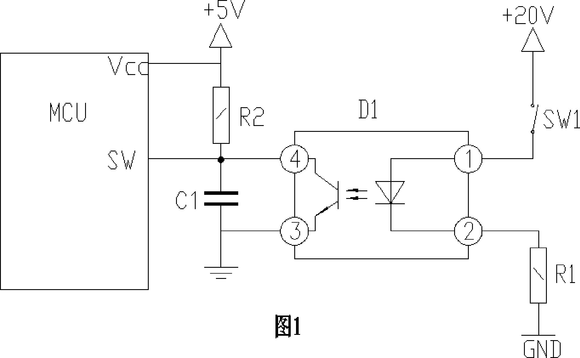
[0020] The control system of this example includes MCU and water flow detection circuit, as shown in Figure 1. The water flow detection circuit is composed of +20V power supply, photocoupler D1, resistors R1, R2, capacitor C1, and water flow switch SW1. The working principle of the circuit is as follows:

[0021] When the water flow switch SW1 is disconnected, the current flowing through the resistor R1 and pins 1 and 2 of the photocoupler D1 is 0, and the pins 3 and 4 of the photocoupler D1 are cut off and in the disconnected state. The SW input of the MCU The terminal is pulled up to a high level (+5V) by the resistor R2. Capacitor C1 has a filtering effect, so that the level signal entering the MCU is clean and without interference, and resistor R1 has a current limiting effect. When the water flow switch SW1 is turned on, the current flowing through the resistor R1 and pins 1 and 2 of the photocoupler D1 is about 4mA, the pins 3 and 4 of the photocoupler D1 are saturated...


PUM


Abstract

The invention relates to the central air-conditioning control system, in particular involving the detection of the modular cold unit water flow switch and its control method. The invention discloses a control system of DC signal detect the water flow and its control method. The technology program is, the cold unit control system includes the MCU and water flow detection circuit, and its characteristics are that the DC output signal of water flow detection circuit connects the MCU. Based on the closed signal of the water flow detection switch and the work condition of the pump, the invention method judges whether the circulating water system fault, or water flow switch fault. The beneficial effects of the invention is that reduced the complexity and cost structure of the control system, can provided the accurate fault information of the circulating water system to the control system, reduced the loss of the manmade downtime, improved the reliability of the system.

Description

technical field [0001] The invention relates to a central air-conditioning control system, in particular to a detection and control method for a water flow switch of a modular chiller. Background technique [0002] The control system of existing modular chillers generally includes an MCU (microprocessor) and a water flow detection circuit. In order to detect whether the circulating water system is working normally, most of them use alternating current to detect the opening or closing signal of the water flow switch to realize starting, protecting or shutting down, so as to achieve the purpose of controlling or protecting the system. During the transmission process of the water flow switch signal, a power resistor needs to be used to limit the current, and a matching shaping circuit is required to shape the signal level. In the control system of the prior art, not only the structure of the water flow detection circuit is complex, but also because the transmission is an AC si...

Claims


Application Information

Patent Timeline
IPC IPC(8): F25B49/00F25B11/00
Inventor 潘宇刘运中刘启武赵寰钱中源
Owner 四川长虹空调有限公司
Why Eureka
Try Eureka